
Power control in mobile radio telephone systems when transmission is interrupted

Inactive Publication Date: 2006-03-28
SIEMENS AG
View PDF11 Cites 35 Cited by
  • Summary
  • Abstract
  • Description
  • Claims
  • Application Information

AI Technical Summary

Benefits of technology

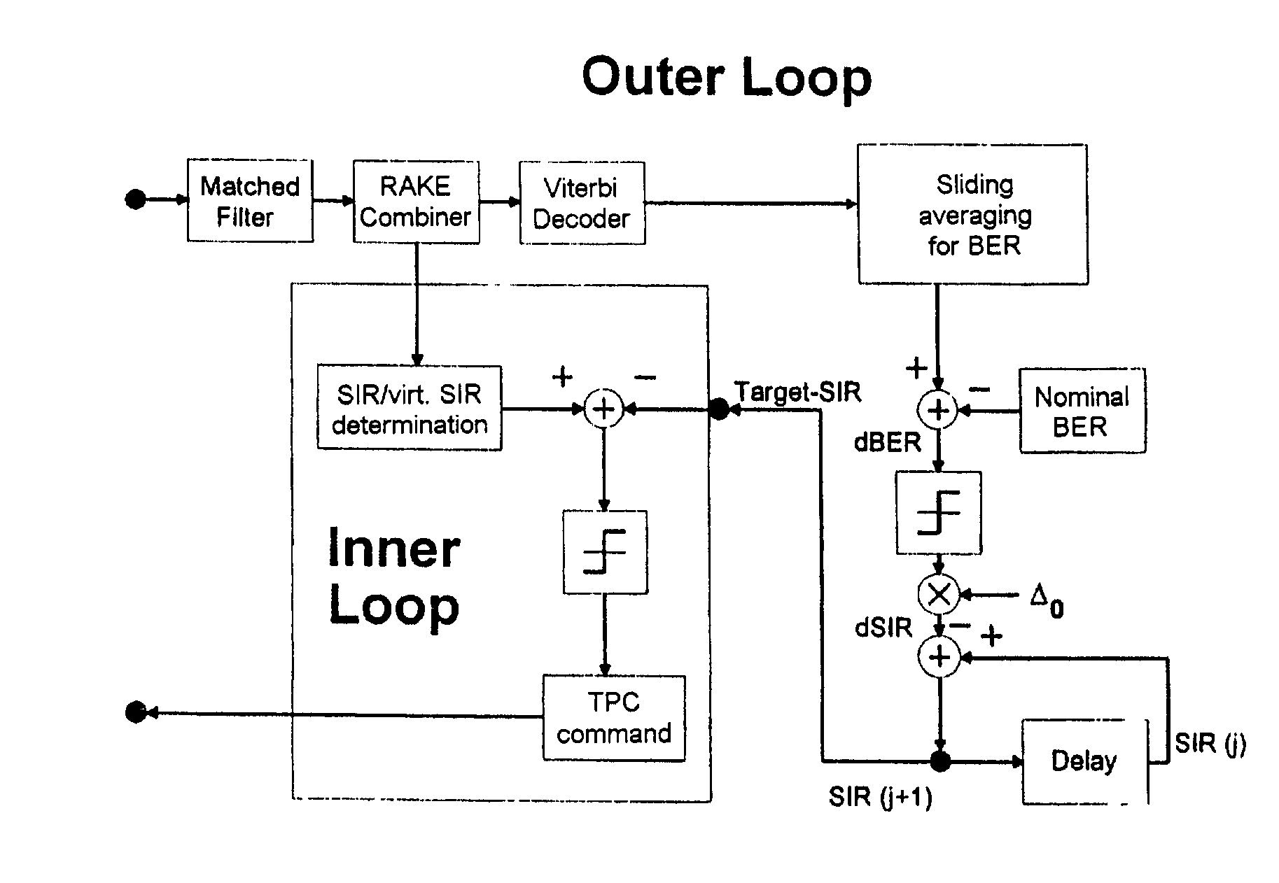
[0008]Thus, according to the present invention, an “external” signal is advantageously used in order to maintain the inner power control loop and the outer power control loop when there is no data signal. Power control commands are preferably transmitted unchanged to the transmitter in this case. Due to the lack of data or data signals to be transmitted, the transmitter knows that it must first of all accumulate the commands, and must then correct the transmission power by the accumulated value at a later stage.
[0009]In principle, the commands can be added up in the transmitter and in the receiver. If they are added up in the transmitter, the sum can be transmitted to the receiver at regular or irregular time interva...

Problems solved by technology

The operation of the method is thus also possible, in particular, when the regular transmission of power control commands is impossible.

Method used


Image

  • Power control in mobile radio telephone systems when transmission is interrupted
  • Power control in mobile radio telephone systems when transmission is interrupted
  • Power control in mobile radio telephone systems when transmission is interrupted

Examples


Embodiment Construction

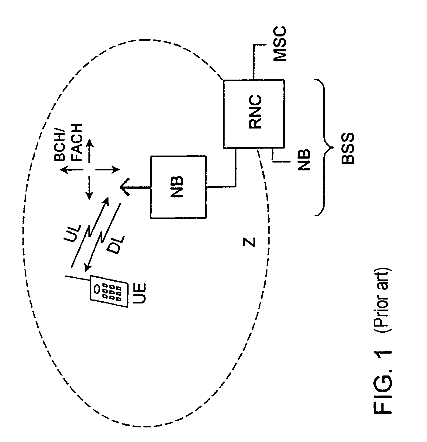
[0017]FIG. 1 shows a part of a mobile radio system as an example of the structure of a radio communications system. A mobile radio system in each case includes a large number of mobile switching centers MSC, which are part of a switching network (SSS—Switching Subsystem) and are networked with one another, and / or produce access to a landline network, as well as one or more base station systems BSS (BSS—Base Station Subsystem), which are connected to the mobile switching centers MSC. A base station system BSS also has at least one device RNC (RNC—Radio Network Controller) for assigning radio resources, as well as at least one base station NB (NB—Node B) respectively connected thereto. A base station NB can set up connections via a radio interface to communication terminals or subscriber stations UE (UE—User Equipment), such as mobile stations or other types of mobile and stationary terminals. At least one radio cell Z is formed by each base station NB. The size of the radio cell Z is...


PUM


Abstract

A method is provided for transmission power control and a radio communications system having at least one first and one second station which communicate with each other, wherein a receiving one of the stations determines the reception power of a signal which is sent from the other station, and the transmitting station transmits a power control instruction, with the receiving station using a signal which is independent of communication data in order to determine the power control instruction.

Description

BACKGROUND OF THE INVENTION[0001]In radio communications systems, such as the second generation European Mobile Radio System GSM (Global System for Mobile Communications), information such as speech, picture information or other data is transmitted on electromagnetic waves via a radio interface. The radio interface relates to a connection between a base station and a large number of subscriber stations, in which case the subscriber stations may, for example, be mobile stations or fixed-position radio stations. The electromagnetic waves are, in this case, transmitted at carrier frequencies which are in a frequency band provided for the respective system. Frequencies in the frequency band around 2000 MHz have been provided for future radio communications systems, such as the UMTS (Universal Mobile Telecommunications system), or other 3rd generation systems. Two modes are envisaged for the third mobile radio generation UMTS, with one mode being referred to as FDD operation (Frequency D...

Claims


Application Information

Patent Timeline
IPC IPC(8): H04B7/00H04B7/005
CPCH04W52/265H04W52/283H04W52/288H04W52/282H04W52/12H04W52/16H04W52/221H04W52/50H04W52/36H04W52/44H04W52/54
Inventor OESTREICH, STEFAN
Owner SIEMENS AG
Learn More