Chuck
a technology of chuck and chuck body, which is applied in the field of chuck, can solve the problems of inability to accurately cut, and achieve the effects of reducing friction resistance, preventing deformation, and preventing adverse effects of torsional deformation
- Summary
- Abstract
- Description
- Claims
- Application Information
AI Technical Summary
Benefits of technology
Problems solved by technology
Method used
Image
Examples
first embodiment
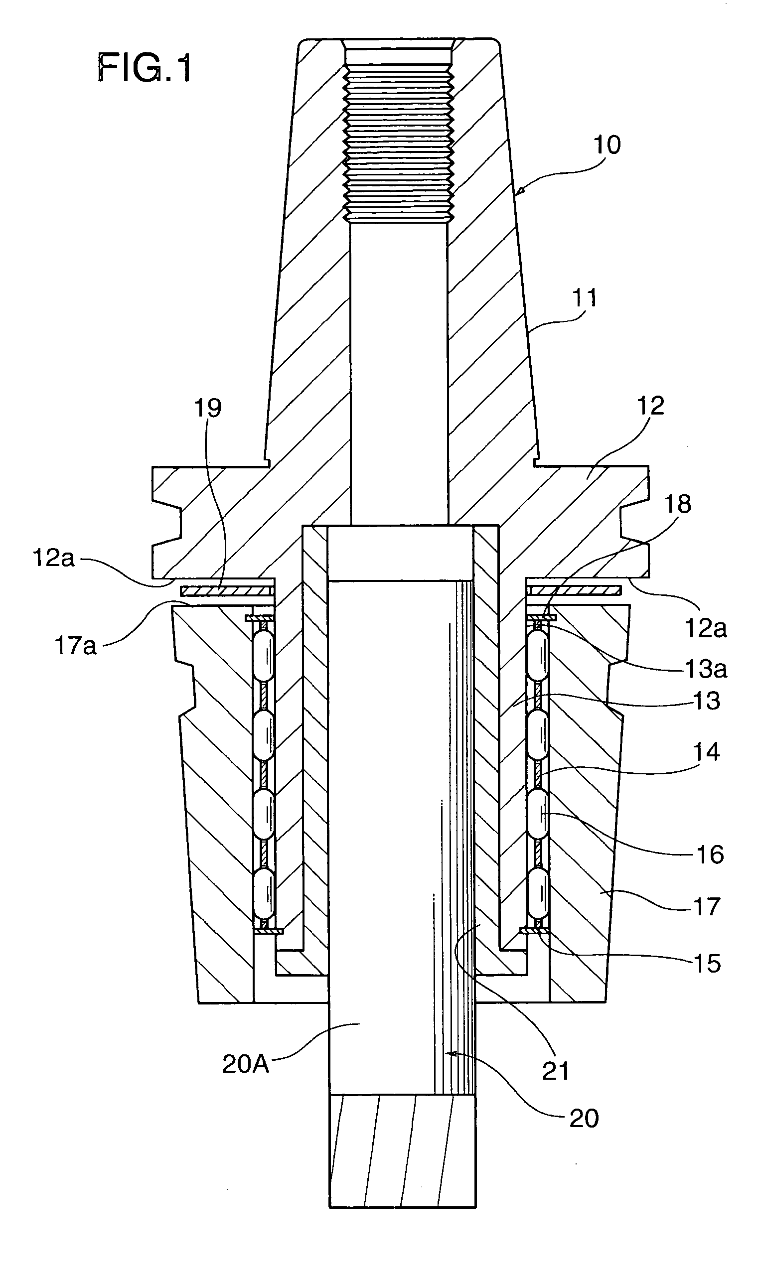
[0038]FIG. 1 shows a cross-sectional view of a chuck according to a first embodiment of the present invention.
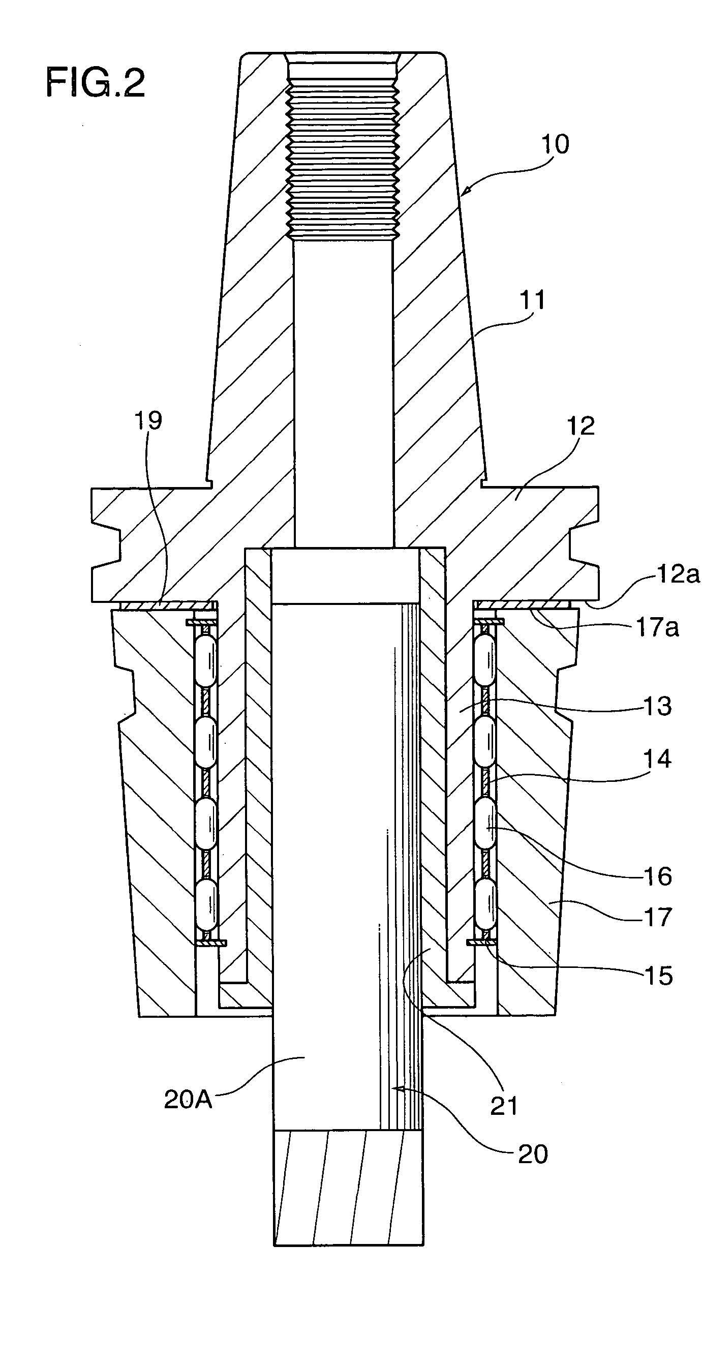
[0039]As shown in FIG. 1, the tool chuck has a holder body 10, which has a tapered shank portion 11 to be inserted into a spindle of an unillustrated machine tool, a gripping flange 12 formed at the larger-diameter end of the tapered shank portion 11, and a chuck sleeve 13 that extends from an end surface 12a of the flange 12 opposite the tapered shank portion 11. The chuck sleeve 13 extends in the direction away from the tapered shank portion 11 such that the axis of the chuck sleeve 13 coincides with the axis of the tapered shank portion 11. The chuck sleeve 13 has a tapered outer circumferential surface 13a whose diameter decreases from the bottom end adjacent to the flange 12 toward the tip end.
[0040]Reference numeral 14 denotes a roller-retaining sleeve fitted onto the outer circumference of the chuck sleeve 13 with a clearance therebetween. The diameter of the roller r...
second embodiment
[0047]Next, a chuck according to a second embodiment of the present invention will be described.
[0048]The chuck of the second embodiment shown in FIG. 4 is identical with that of the first embodiment, except that in the end surface 12a of the flange 12 opposite the tapered shank portion, a groove 22 having a predetermined depth (approximately 2 to 5 mm) is formed, at the bottom portion of the chuck sleeve 13 through which the chuck sleeve 13 is joined with the flange 12, such that the groove 22 extends along the outer circumference of the chuck sleeve 13 to form a ring-like shape. The ring-shaped, groove 22 allows the chuck sleeve 13 to be extended toward the flange 12 side without changing the tool length L1 of the holder body 10.
[0049]By virtue of the above-described structure, the radially inward elastic deformation of the chuck sleeve 13 in a bottom end area adjacent to the flange 12 is made substantially equal to that in the remaining area of the chuck sleeve 13.
[0050]Since the...
third embodiment
[0053]Next, a chuck according to a third embodiment of the present invention will be described with reference to FIGS. 6 to 8.
[0054]In FIG. 6, structural elements identical with those shown in FIGS. 1 to 5 are denoted by the same reference numerals, and their repeated descriptions are omitted. Only portions different from those shown in FIGS. 1 to 5 will be mainly described.
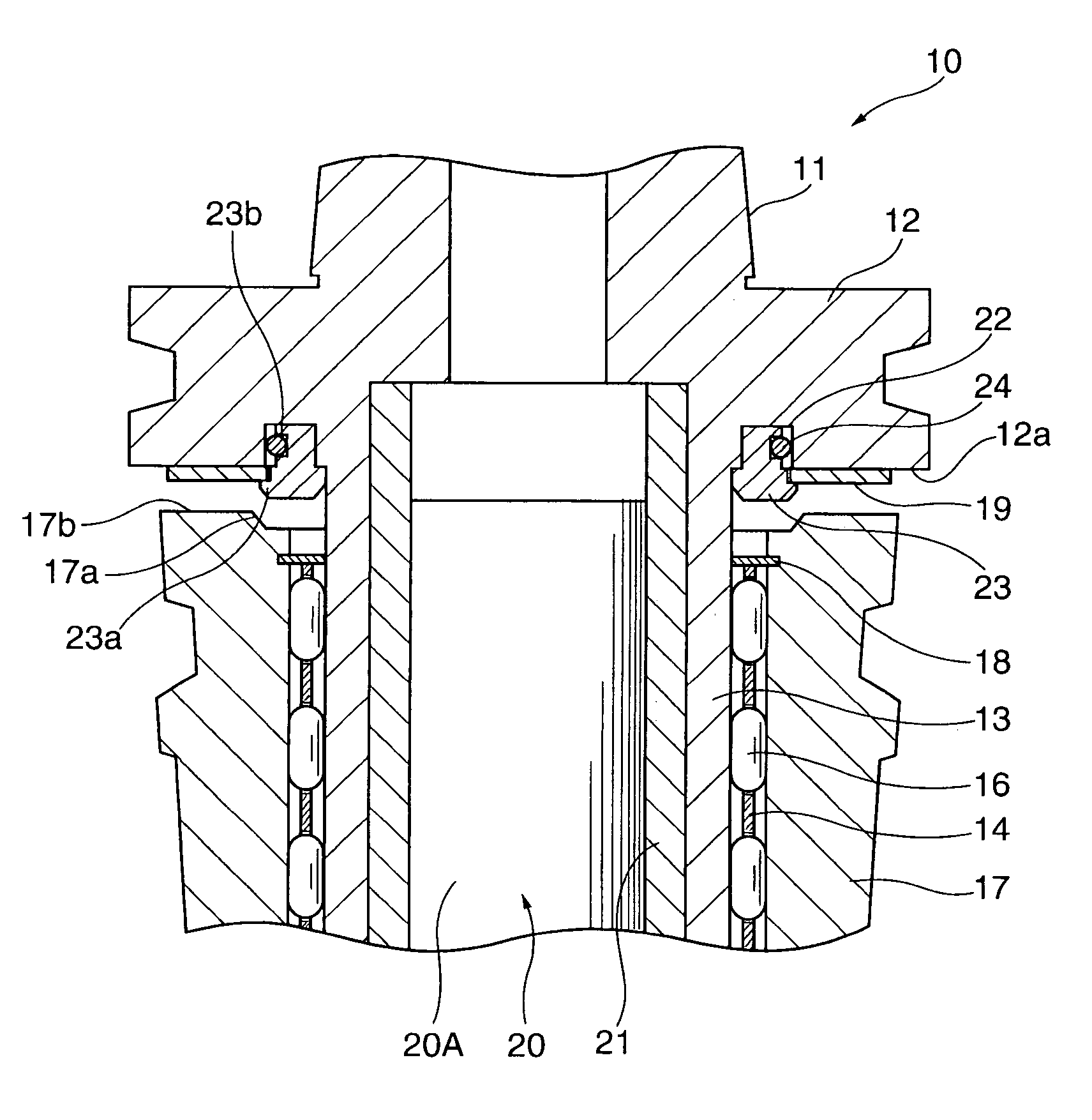
[0055]The feature of the chuck according to the third embodiment resides in that the annular groove 22 is formed in the end surface of the flange 12 in order to increase the effective length of the chuck sleeve 13, and that a thrust-member holder 23 is provided in order to prevent play or movement of the thrust member 19 along the axial direction.
[0056]In the chuck of the third embodiment, the thrust-member holder 23 is fitted into the central opening of the thrust member 19. The thrust-member holder 23 has an opening for allowing passage of the chuck sleeve 13 therethrough, and a stepped portion 23a which projec...
PUM
 Abstract
Description
Claims
Application Information
 - R&D
- Intellectual Property
- Life Sciences
- Materials
- Tech Scout
- Unparalleled Data Quality
- Higher Quality Content
- 60% Fewer Hallucinations
Browse by: Latest US Patents, China's latest patents, Technical Efficacy Thesaurus, Application Domain, Technology Topic, Popular Technical Reports.
© 2025 PatSnap. All rights reserved.Legal|Privacy policy|Modern Slavery Act Transparency Statement|Sitemap|About US| Contact US: help@patsnap.com


