Microwave drying method

a drying method and microwave technology, applied in the direction of electric/magnetic/electromagnetic heating, furniture, lighting and heating apparatus, etc., can solve the problem of difficult uniform drying of all objects laid within the same space, and achieve the effect of retaining productivity (mass productivity) at a high level

Active Publication Date: 2006-03-28
NGK INSULATORS LTD
View PDF5 Cites 52 Cited by
  • Summary
  • Abstract
  • Description
  • Claims
  • Application Information

AI Technical Summary

Benefits of technology

[0011]According to the microwave drying method of the present invention, when a plurality of objects are simultaneously laid for drying in the same space, all the objects can be uniformly dried. In addition, high productivity can be ensured if the distance between at least a pair of the objects located adjacently that have the shortest distance therebetween among any pair of the objects located adjacently is set at a length as close as ¾ of the wavelength of the microwave, which is the lower limit specified by the present invention, for example, in a range of ¾ or more, but not more than the wavelength of the microwave used, because this distance allows as many objects as possible to be dried uniformly and efficiently at the same time. The expression “shortest distance between the objects (to be dried)” means, in the present specification, the shortest distance between at least one pair of the objects to be dried that are laid adjacently at the nearest position each other. This distance is sometimes referred to “the (mutual) distance between them”, too. Therefore, at least a considerable number of pairs of the adjacent objects laid at the nearest position can meet this shortest distance, more effective drying can be achieved.

Problems solved by technology

However, too narrow a distance between the objects to be dried causes a problem.
This is because the uniform drying of all the objects laid within the same given space becomes difficult since the drying conditions would often vary, one by one within the objects laid in the same given space, depending upon the mutual distance between them.

Method used


Image

  • Microwave drying method
  • Microwave drying method

Examples


example 1

[0021]A composition containing powders convertible into cordierite by firing, a binder, and a surfactant were kneaded with an addition of 22 wt % of water and the resultant was extruded to produce a given number of formed honeycomb structures, each having a diameter of 144 mm, a length of 220 mm, a wall thicknesses of 75 μm, and 600 cells / in2 (93 cells / cm2).

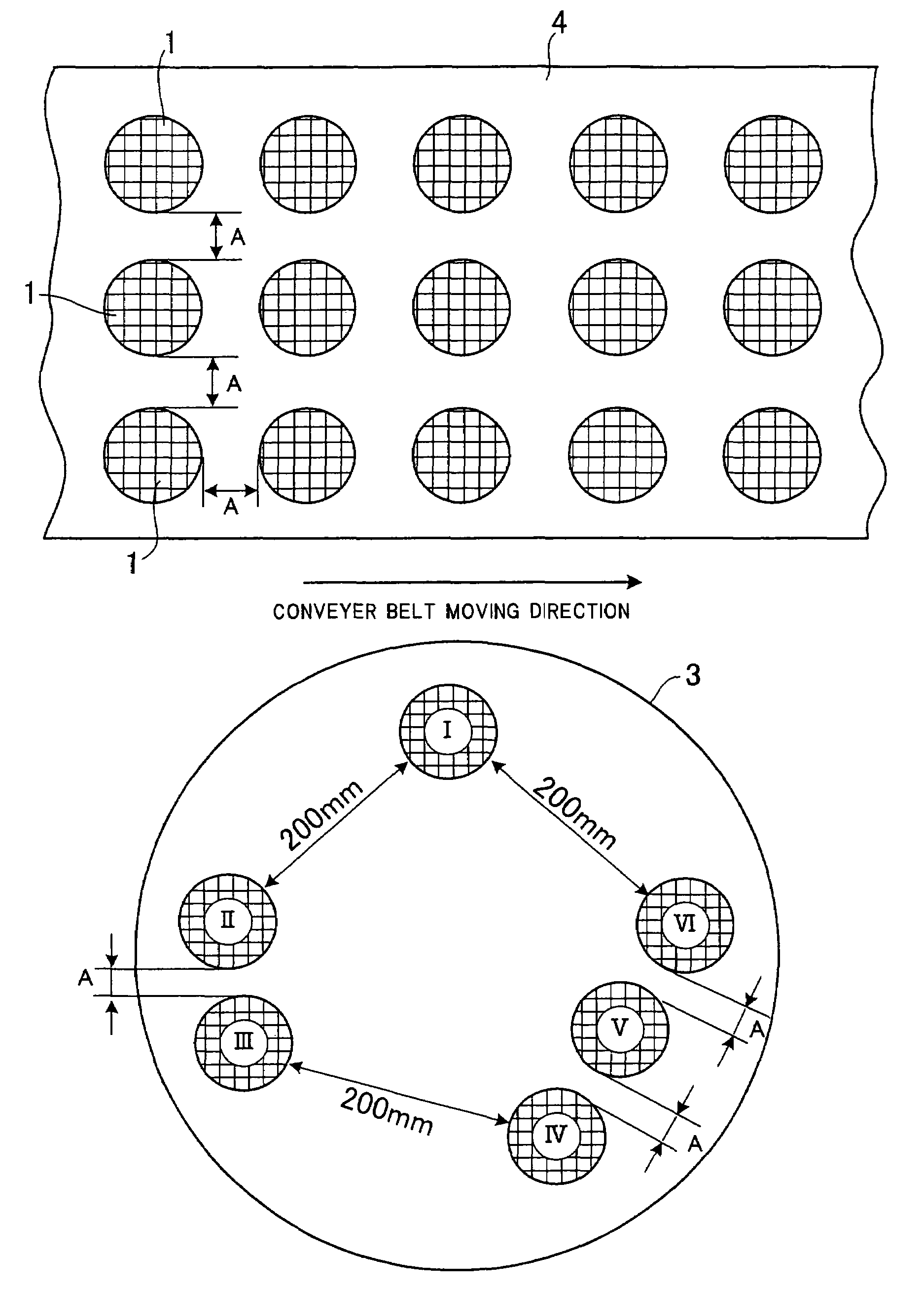
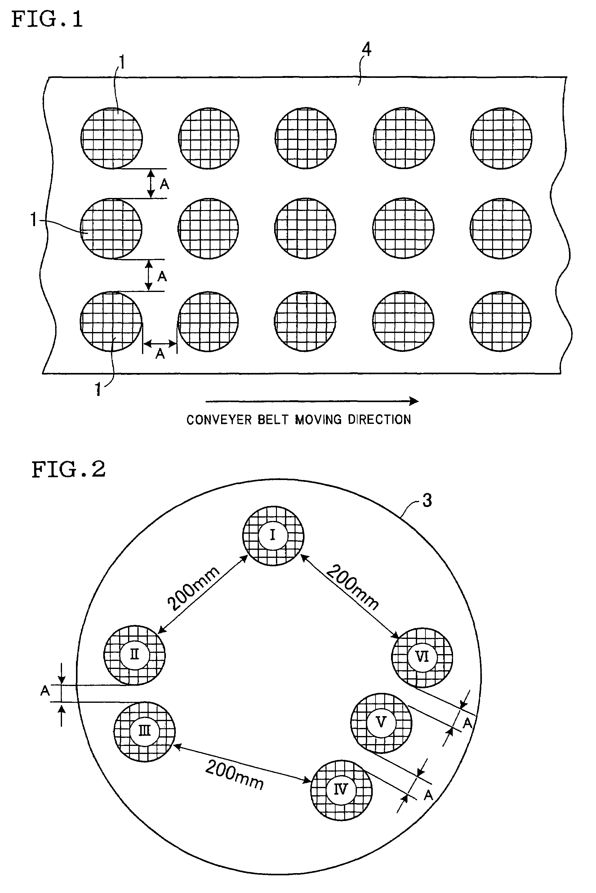
[0022]The six honeycomb molded products I–VI were laid as shown in FIG. 2, keeping the predetermined distances, respectively, on a turn table 3 with a diameter of 1.2 m in a batch-type microwave oven having a microwave output of 15 kW to examine the effect of the distance between the honeycomb structures on drying them. Therefore, in the case of the honeycomb structure I, its shortest distance to the nearest adjacent honeycomb structures was set at 200 mm. The shortest distances, that is, the distances A between honeycomb structures II and III, IV and V, V and VI were varied, depending upon the predetermined distances of 0 mm, 60...

example 2

[0026]The formed honeycomb structures with the same size as those in Example 1 were prepared. The formed honeycomb structures were laid as the objects 1 to be dried, shown in FIG. 1, on the conveyer belt 4 in a continuous-type microwave oven with a microwave output of 200 kW, and dried by irradiating a microwave at a wavelength of 120 mm while changing the mutual distance A between the formed honeycomb structures from 0 mm, 60 mm, 90 mm, and 120 mm to determine the rate of water removal at each distance A. As a result, as experienced in the batch-type drier used in Example 1, when the mutual distance A as the shortest distance between at least a pair of the honeycomb structures located adjacently at the nearest distance was 90 mm or more, all the formed honeycomb structures were almost uniformly dried, with almost no difference in the water removal rate among the formed honeycomb structures.

[0027]The method of the present invention is particularly suitably applied to drying formed h...


PUM

PropertyMeasurementUnit
wavelengthaaaaaaaaaa
distanceaaaaaaaaaa
distanceaaaaaaaaaa

Abstract

A method for drying a plurality of objects in a same space using a microwave, a method of uniformly drying all the objects to be dried while retaining the high productivity (mass productivity) as much as possible is provided. The method comprises laying a plurality of objects to be dried apart from each other by keeping, as a shortest distance between at least one pair of adjacent objects among them a distance equivalent to ¾ or more of the wavelength of the microwave to be used and irradiating them with the microwave.

Description

BACKGROUND OF THE INVENTION[0001]1. Field of the Invention[0002]The present invention relates to a method of drying a wet green body such as an undried green honeycomb structure using a microwave.[0003]2. Description of the Prior Art[0004]A honeycomb structure is widely used for a catalyst carrier and various filters, and recently has also attracted attention as a diesel particulate filter (DPF) for capturing particulates discharged from a diesel engine.[0005]Honeycomb structures are made of a ceramics as major components. These honeycomb structures are usually manufactured by preparing clay by kneading a mixture of ceramic raw materials with water and various additives, extruding thus prepared clay into a formed product to obtain undried green honeycomb structures (hereinafter sometimes referred to as formed honeycomb structures), drying thus formed green honeycomb structures, and firing the resultant dried honeycomb structures.[0006]A well known method of drying the formed honeyco...

Claims


Application Information

Patent Timeline
Patent Type & Authority Patents(United States)
IPC IPC(8): F26B3/34B28B11/00B28B11/24F26B3/347
CPCB28B11/241F26B3/347B28B11/243F26B2210/02
Inventor KATO, SHIGEKI
Owner NGK INSULATORS LTD
Why Eureka
Try Eureka