
System for allocating resources in a communication system

a communication system and resource allocation technology, applied in the field of communication systems, can solve the problems of affecting the limited bandwidth of the communication node in such systems, and the inability to serve certain subscribers, so as to enhance the overall data throughput of the common node and the rate of higher rate

Inactive Publication Date: 2006-03-21
QUALCOMM INC
View PDF12 Cites 94 Cited by
  • Summary
  • Abstract
  • Description
  • Claims
  • Application Information

AI Technical Summary

Benefits of technology

[0012]It is another object of an embodiment of the present invention to provide a system and method for optimally allocating data transmission resources among a plurality of subscribers subject to a fairness criteria according to a network policy.
[0014]It is yet another object of an embodiment of the present invention to provide a system and method for enhancing the efficiency of transmitting data to a plurality of subscribers in a variable-rate data transmission network by allocating transmission resources to each individual subscriber based upon the rate at which the subscriber can receive transmitted data.
[0016]The resource scheduler may maintain the weights associated with each customer node based upon the instantaneous rate at which the customer node can receive data from the common node. The resource scheduler may then favor transmission to the customer nodes having the higher rates of receiving data. By maintaining a weight associated with each of the customer nodes, and selecting individual customer nodes to seize the common node, the scheduler can optimally allocate resources to the customer nodes subject to a fairness criteria.

Problems solved by technology

A communication node in such systems typically has a limited bandwidth for either transmitting information to or receiving information from each subscriber in the network at any point in time.
This may result in an under utilization of certain time intervals by certain subscribers.
Similarly, other subscribers may have communication resource requirements which exceed the allocated time interval, leaving these subscribers under served.

Method used


Image

  • System for allocating resources in a communication system
  • System for allocating resources in a communication system
  • System for allocating resources in a communication system

Examples


second embodiment

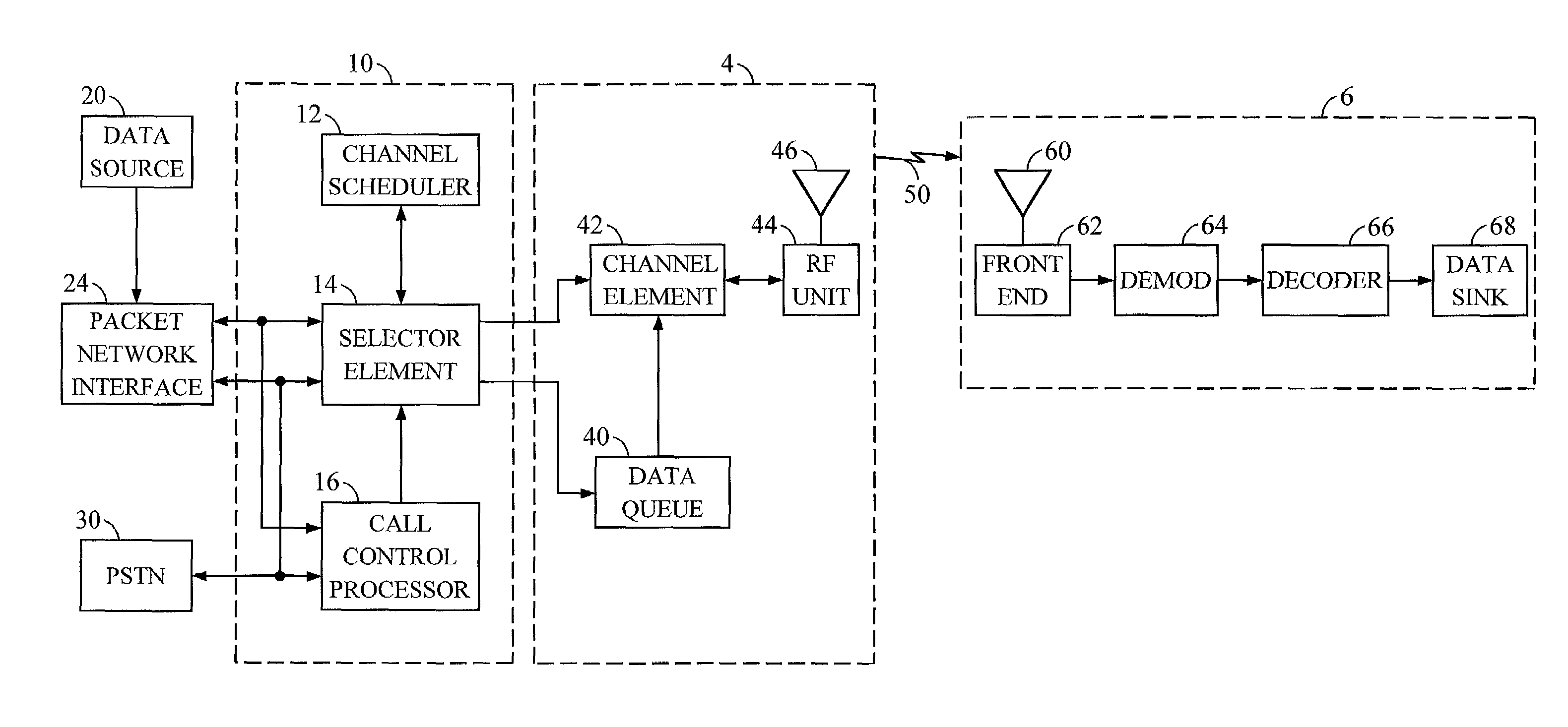
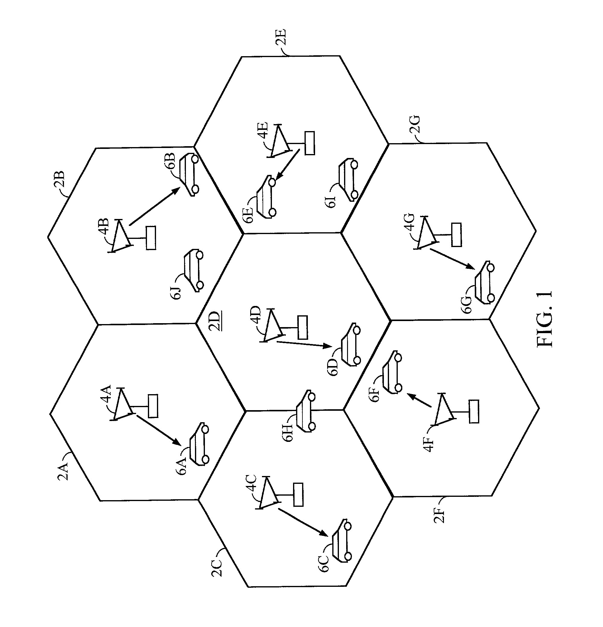
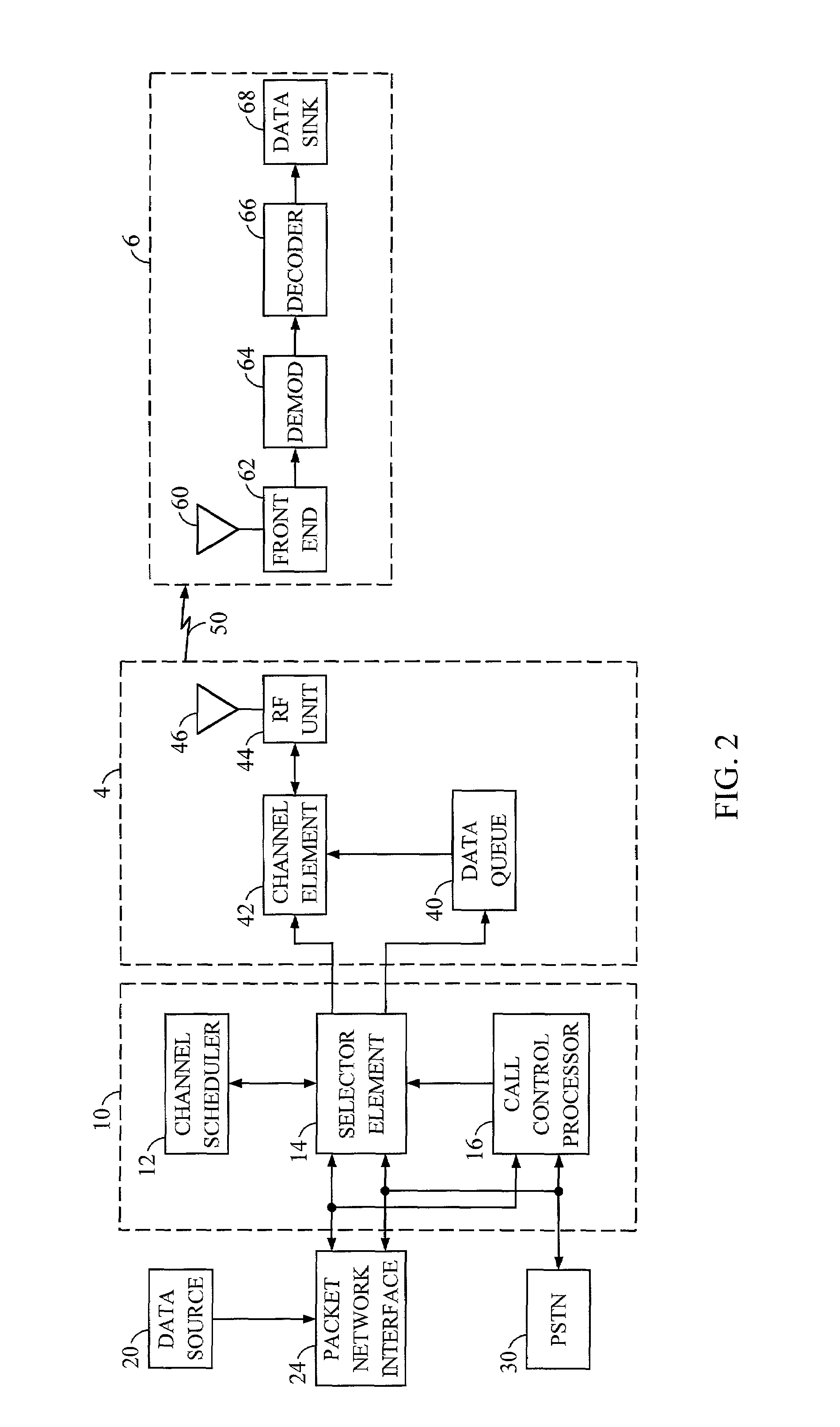
[0064]FIGS. 7A through 7D show a flow diagram illustrating the logic performed at the step 110 for selecting a queue for transmission to an associated remote station 6. In this embodiment, it is assumed that each base station 4 periodically transmits a control signal to all associated remote stations 6 having a fixed duration (such as eight to sixteen time slots). According to an embodiment, the base station 4 transmits this control signal once every 400 msec. During this control transmission, no data from any data queue 40 (FIG. 2) may be transmitted to an associated remote station 6. An objective of the embodiment shown at FIGS. 7A and 7B is to select only those data queues which may completely transmit for a service interval having a length determined at step 108 before the beginning of the next control signal transmission.

[0065]Steps 499 through 503 filter all of the queues to determine which queues are candidates for completion before the beginning of the next control signal tr...

third embodiment

[0067]FIGS. 8A and 8B show a flow diagram illustrating the logic executed at step 110 at FIG. 3 for selecting a queue for transmission. In this embodiment, subscribers of select remote units 6 are guaranteed a minimum average rate of data transmission. For each such premium remote unit, the channel scheduler 12 maintains a timer which alerts the channel scheduler 12 to schedule a transmission to its premium queue, regardless of the weights associated with the remaining queues. The time interval for the particular timer is determined based upon the average data rates guaranteed to the customer, the service interval assigned to that data queue at step 108 (see center column of Table 1), and any instantaneous data rate for receiving data determined at step 106. Thus, the time interval associated with the premium queue timer is dynamic with respect to these values. According to an embodiment, the timer interval is determined whenever the timer is reset as follows:

[0068]

Tj =Data_Size (Lj...


PUM


Abstract

A communication network having a plurality of subscriber units receive a finite resource from a common node is disclosed. Individual subscriber units may seize the finite resource of the common node to the exclusion of all other subscriber units in the network. A scheduler allocates the finite resource to the individual subscriber units based upon a weight associated with the individual subscriber units. The scheduler determines the weight for each of the subscriber units based upon an instantaneous rate of consuming the finite resource.

Description

CROSSREFERENCE TO RELATED APPLICATION[0001]This application is a continuation of U.S. application Ser. No. 09 / 229,432, filed on Jan. 13, 1999, entitled “System for Allocating Resources in a Communication System,” now U.S. Pat. No. 6,229,795, issued on May 8, 2001.BACKGROUND[0002]1. Field of the Invention[0003]Embodiments disclosed herein relate to communication systems. Particularly, these embodiments are directed to allocating communication resources among the plurality of subscribers to a communication system.[0004]2. Related Art[0005]Several solutions have been presented to address the problem of allocating limited communication resources provided by a single node in a communication system among a plurality of subscribers. It is an objective of such systems to provide sufficient resources at the nodes to satisfy the requirements of all subscribers while minimizing costs. Accordingly, such systems are typically designed with the objective of efficient allocation of resources among...

Claims


Application Information

Patent Timeline
Patent Type & Authority Patents(United States)
IPC IPC(8): H04J3/16H04J3/22H04L12/28H04L12/56H04L29/06H04W16/04H04W72/04H04W72/06H04W72/12
CPCH04L12/5693H04L47/14H04L47/522H04L47/562H04W72/1257H04L47/6255H04L47/6265H04W72/1252H04L47/621H04L47/15H04W16/04H04W72/1221H04W28/0231H04W72/52H04W72/535H04W72/04H04W72/12H04L47/50H04W8/04
Inventor PANKAJ, RAJESHSINDHUSHAYANA, NAGABHUSHANA T.
Owner QUALCOMM INC
Learn More