
Transflective liquid crystal display with partial switching

a liquid crystal display and partial switching technology, applied in optics, instruments, nanotechnology, etc., can solve the problems of low reflection rate, low light intensity, and display washed out completely, and achieve high reflection ra

Inactive Publication Date: 2006-03-21
CENT FLORIDA UNIV OF +1
View PDF13 Cites 30 Cited by
  • Summary
  • Abstract
  • Description
  • Claims
  • Application Information

AI Technical Summary

Benefits of technology

[0021]A primary objective of the invention is to provide high reflection (R) and transmission(T) transflective liquid crystal displays (TLCDs) with a single gap technique without having to use a double cell gap.
[0022]A secondary objective of the invention is to provide high reflection (R) and transmission (T) transflective liquid crystal displays (LCDs) having a high performance for displaying high quality images when an ambient light is not bright enough, particularly on color reflective displays.
[0025]Also in accordance with this invention there is provided a single gap, transflective liquid crystal display (TLCD) comprising: a single gap liquid crystal display (LCD) having transmissive pixels (T) and reflective pixels (R); and, means for reducing birefringence change Δn of the reflective pixels (R) in a single gap liquid crystal display (LCD) so that total retardation Δnd of the reflective pixels (R) is approximately equal to total retardation Δnd of transmissive pixels in the single gap LCD.

Problems solved by technology

However, their power consumption is high due to the need of a backlight.
At bright ambient, e.g. outdoor, the display is washed out completely and hence loses its legibility.
However, the readability of a reflective LCD is lost under poor ambient light.
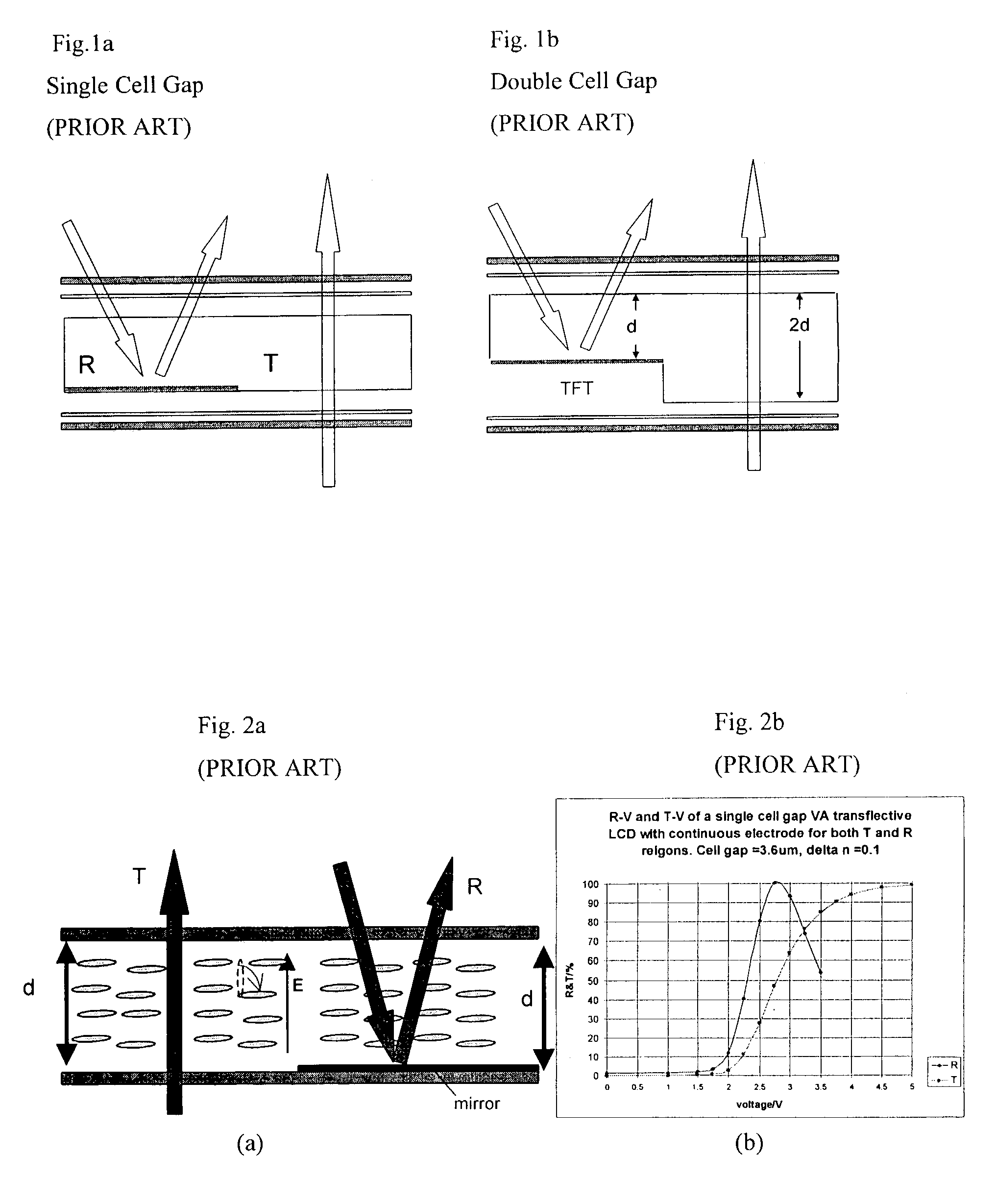
Single cell gap transflective LCD (TLCD) usually leads to low efficiency for the transmission T. In order to attain high T and R, one often needs to turn to the double cell gap approach.
This approach however leads to a much more complicated structure as well as a very demanding fabrication process.
This good control can be difficult which results in non-uniformity in the cell gap and hence deterioration of the LCD optical performance.
So far there have been very few approaches that can overcome the problems of the prior art teachings, i.e. to attain high light efficiencies using only a single cell gap.
This approach is however very difficult to be achieved for mass production using the present LC technology.

Method used


Image

  • Transflective liquid crystal display with partial switching
  • Transflective liquid crystal display with partial switching
  • Transflective liquid crystal display with partial switching

Examples

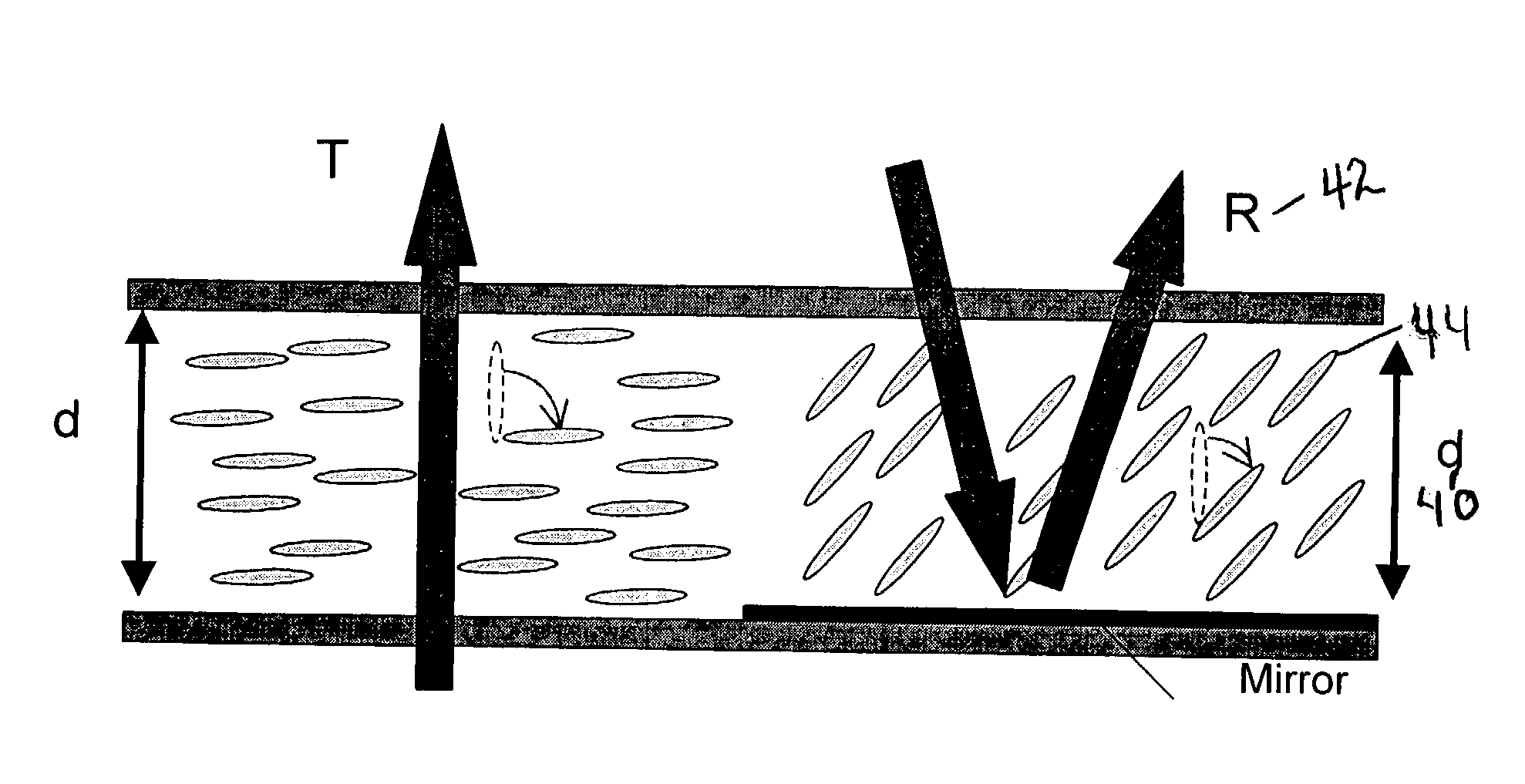
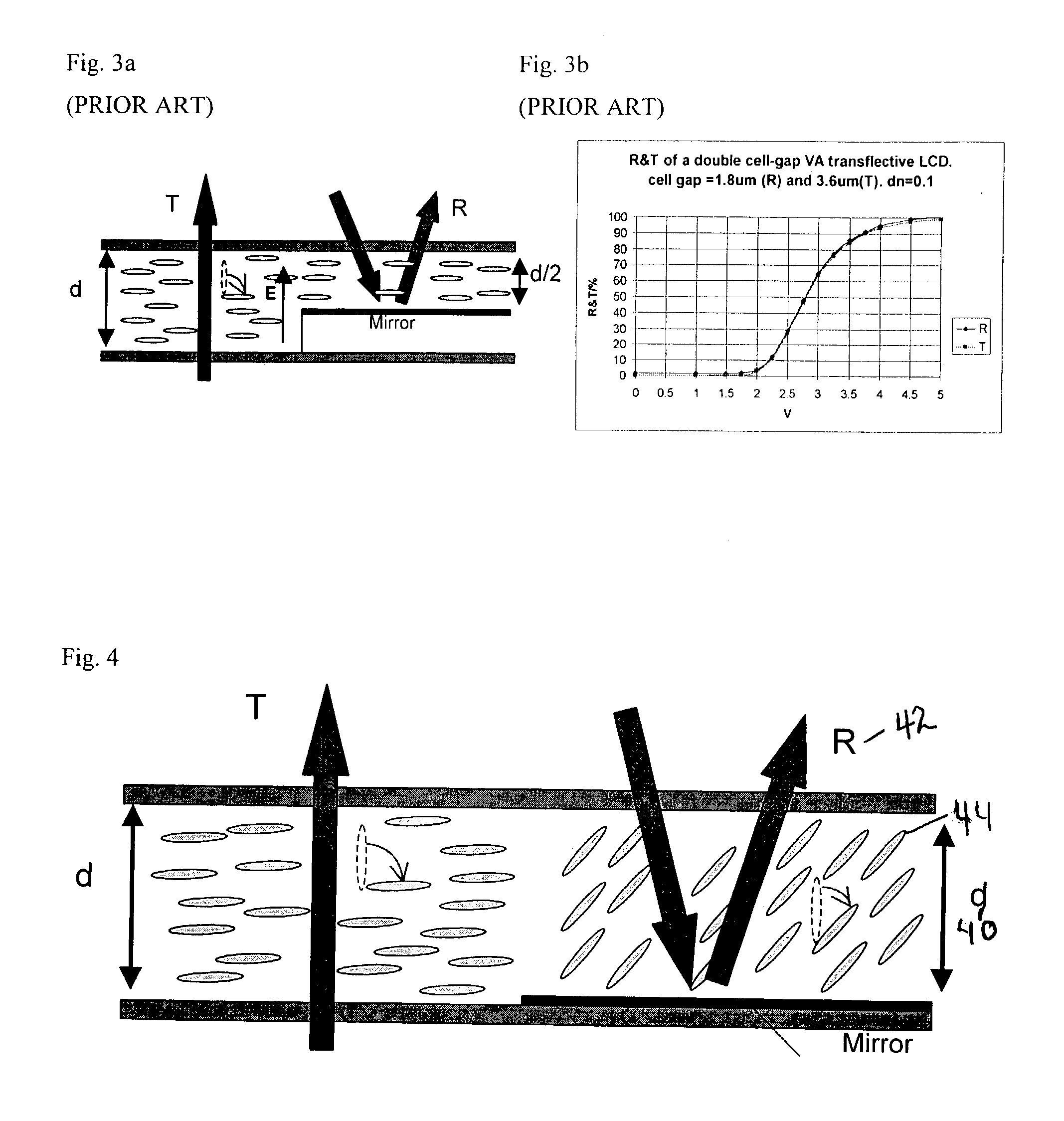

Embodiment Construction

[0036]Before explaining the disclosed embodiment of the present invention in detail, it is to be understood that the invention is not limited in its application to the details of the particular arrangement shown since the invention is capable of other embodiments. Also, the terminology used herein is for the purpose of description and not of limitation.

[0037]In accordance with invention disclosed hereafter, it has been found that instead of reducing the cell gap from d to d / 2, one can reduce the birefringence change from Δn to Δn / 2 in the R region by the use of partial switching. The molecules are switched by approximately 45° instead of the normal 90°. In this case the resultant retardation change for the double-path R remains at (Δn / 2)×(2d)=Δnd, which is the same as that of T. This leads to high light efficiency for both T and R using the simple single cell gap structure.

[0038]What follows is a demonstration of a suitable scheme for generating such kind of partial switching. This ...


PUM


Abstract

A high reflection and transmission transflective liquid crystal display (TLCD) that requires only a single cell gap. Instead of reducing the cell gap of the R sub-pixel region, the invention reduces the birefringence change Δn of reflective pixels (R) so that the total retardation change Δnd of R is equal to that of the transmissive pixels (T). This is realized by a partial switching of the pixels of approximately 45 degrees which occurs in the reflective pixel (R) region of the single cell gap by applying fringing fields, generated by a discontinuous electrode, to the molecules in the reflective pixel (R) region of the cell gap.

Description

[0001]This invention claims the benefit of priority to U. S. Provisional Patent Application Ser. No. 60 / 376,670 filed Apr. 30, 2002.FIELD OF INVENTION[0002]This invention relates to transmission type liquid crystal displays (LCD), and in particular to methods and apparatus for producing transflective liquid crystal displays (TLCD) with partial switching capability.BACKGROUND AND PRIOR ART[0003]Conventional transmission-type Liquid Crystal Displays (LCDs) exhibit high contrast ratios with good color saturation. However, their power consumption is high due to the need of a backlight. At bright ambient, e.g. outdoor, the display is washed out completely and hence loses its legibility. On the other hand, a reflective LCD uses ambient light for reading out the displayed images and hence retains its legibility under bright ambient. Their power consumption is reduced dramatically due to the lack of a backlight. However, the readability of a reflective LCD is lost under poor ambient light. ...

Claims


Application Information

Patent Timeline
IPC IPC(8): G02F1/1335G02F1/13G02F1/017G02F1/1343
CPCB82Y20/00G02F1/1343G02F1/133555G02F1/01716G02F2201/128G02F2001/134345G02F1/134345
Inventor CHOI, WING KITWU, SHIN-TSON
Owner CENT FLORIDA UNIV OF
Learn More