
Titanium material superior in upset-forgeability and method of producing the same

a technology of upset forgeability and titanium material, which is applied in the field of titanium material, can solve the problems of reducing the yield of products, affecting the quality of targets, and affecting the quality of targets, and achieves excellent upset forgeability and secure the desired upset forgeability

Inactive Publication Date: 2006-03-21
OSAKA TITANIUM TECHNOLOGIES
View PDF14 Cites 16 Cited by
  • Summary
  • Abstract
  • Description
  • Claims
  • Application Information

AI Technical Summary

Benefits of technology

[0014]The present invention, which has been made in view of the above-mentioned problems occurring in the step of cogging of titanium materials to be worked into targets for sputtering, has for its object to provide a titanium material having good upset forgeability and making it possible to secure a cross-sectional shape infinitely close to a circle in the step of upset forging which is carried out following the step of cylindrical cogging at a final finish outside diameter.
[0015]To achieve the above object, the present inventors made various investigations concerning the technology of warm forging of titanium materials and, as a result, found that the upset forgeability of a titanium material after cylindrical cogging is greatly influenced by the orientation of crystals in the cogging. In other words, this means that the working conditions (material temperature, method of working) in the step of warm forging greatly influence the orientation of crystals and are thus closely associated with the cross-sectional deformation in the subsequent step of upset forging. Further, they found that, for improving the upset forgeability of a cogging, it is necessary for the crystal orientation distribution to show regularity and, at the same time, it is necessary to reduce the dispersion of crystal grain sizes in radial directions from the central portion to the outer layer portion of the cogging.
[0017]For achieving this, it is effective to perform cylindrical cogging in all the stages from the start to the end of warm forging or to perform cylindrical cogging at least in the initial stage or stages of warm forging prior to finish cogging to a cylindrical form as the final shape. Further, it is also possible to secure the desired upset forgeability by performing polygonal forging (e.g. octagonal forging), which resembles cylindrical cogging, in all stages of warm forging. In particular when cylindrical cogging is carried out in all stages of warm forging or at least in the initial stage thereof, the use of round molds as the forging tools is effective.
[0018]FIG. 3 illustrates an example of the round mold to be employed in the practice of the present invention. The round mold according to the invention is constituted of a pair of upper and lower mold parts forming an elliptical hole. A heated material is inserted into this hollow. While the material is moved in the longitudinal direction, it can be uniformly cogged in the manner of free forging by pressing from the upper and lower directions by means of an air hammer, steam hammer or hydraulic press. When the round mold shown in FIG. 3 is used, the titanium material according to the invention can be worked to a shape similar to the final shape and, at the same time, the working force can be caused to uniformly extend to the central portion of the material, whereby the material can show excellent upset forgeability.

Problems solved by technology

In cases where the prior art cogging step, which is carried out in the manner of warm forging as shown in FIG. 1, is employed in working targets for sputtering, significant working losses occur until final products are obtained, decreasing the yield of products, as mentioned above.
When, on the other hand, high-speed forging is employed, there arises the problem that the quality required of targets cannot be secured.

Method used


Image

  • Titanium material superior in upset-forgeability and method of producing the same
  • Titanium material superior in upset-forgeability and method of producing the same
  • Titanium material superior in upset-forgeability and method of producing the same

Examples


example 1

[0048]According to the warm forging process shown in FIG. 4, a cylindrical titanium material was cogged using round molds. The starting material used was a VAR-melted ingot with a diameter of 730 mm φ x a length of 2,500 mm. In the first step, after uniform heating at 850° C. in a heating furnace, cogging was performed to 590 mm φ, to 380 mm φ in the second step, and to 280 mm φ in the third step. Then, in the fourth step, cogging was performed to the finish outside diameter of 165 mm φ using a round mold. Through the first step to the fourth step, uniform heating was conducted between steps to enable warm working at a material temperature of 850 to 500° C. The cogging works were performed while cutting the cogging, on appropriate occasions, to a length enabling easy handling in working.

[0049]The titanium material cogged to the finish outside diameter was cut to a predetermined length (e.g. 200 mm), and the cut pieces were heated at 600° C. in a heating furnace for 2 hours and then ...

example 2

[0054]According to the warm forging process shown in FIG. 5, a titanium material was worked to a cylindrical form as the final shape by cylindrical cogging using round molds in combination with square cogging using flat molds. The starting material used was the same as the one used in Example 1. In the first step, after heating at 850° C. in a heating furnace, cogging was performed to 380 mm φ using a round mold, and to 270 mm φ in the second step using a round mold. Thereafter, in the third step, square cogging was performed to 175 mm square using a flat mold. Then, in the fourth step, cogging was performed to the finish outside diameter of 165 mm φ using a round mold. Through the first step to the fourth step, uniform heating was conducted between steps to enable warm working at a material temperature of 850 to 500° C. The cogging works were performed while cutting the cogging, on appropriate occasions, to a length enabling easy handling in working.

[0055]The titanium material cogg...

example 3

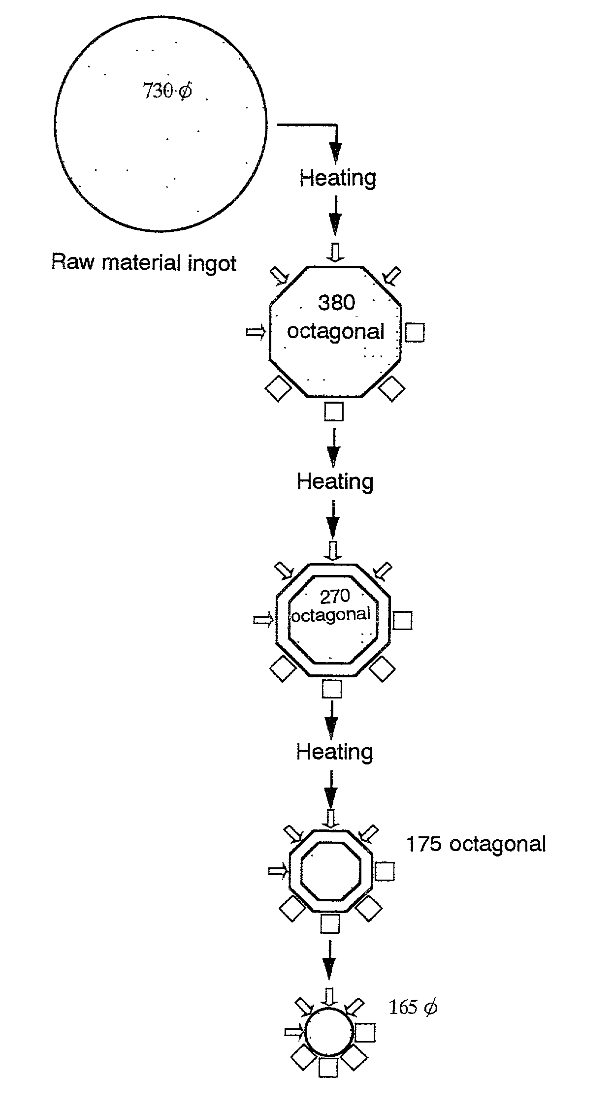
[0056]According to the warm forging process shown in FIG. 6, a titanium material was worked to a cylindrical form as the final shape by performing octagonal cogging in all stages. The starting material used was the same as the one used in Example 1. In the first step, after heating at 850° C. in a heating furnace, cogging was performed to 380 mm octagonal using a flat mold, to 270 mm octagonal in the second step using a round mold, and to 175 mm octagonal in the third step using a flat mold. In the fourth step, cogging was performed to the finish outside diameter of 165 mm φ using a round mold. Through the first step to the fourth step, uniform heating was conducted between steps to enable warm working at a material temperature of 850 to 500° C. The cogging works were performed while cutting the cogging, on appropriate occasions, to a length enabling easy handling in working.

[0057]The titanium material cogged to the finish outside diameter was subjected to forging at an upsetting ra...


PUM

PropertyMeasurementUnit
temperatureaaaaaaaaaa
diameteraaaaaaaaaa
diameteraaaaaaaaaa

Abstract

In finifsh-cogging a high-purity titanium material into a cylindrical form as the final shape, if cylindrical cogging is performed in all stages of warm forging or if cylindrical cogging is performed in the initial stage of the warm forging, there is no need of peripherally restricting the cylindrical cogging material, so that even if longitudinal upset-forging is effected with an upsetting ratio of 2, the condition that the major diameter / minor diameter ratio of the section after forging is not more than 1.01 can be satisfied, developing superior upset-forgeability. This makes it possible, in producing disk-like targets for sputtering, to minimize cutting loss produced during the rolling and machining and to maximize the yield of products; therefore, the material can be widely used as a semiconductor material for electrodes and the like using a high-purity titanium material.

Description

TECHNICAL FIELD[0001]This invention relates to a titanium material excellent in upset forgeability and useful in producing targets for sputtering, various other wrought or processed products and so forth and to a method of producing the same. More particularly, it relates to a titanium material having a uniform forgeable structure and thus having characteristics such that a cross section infinitely close to a circle can be attained after upset forging under compression in the longitudinal direction, without peripherally restricting the cylindrical cogging material, and to a method of producing the same.BACKGROUND ART[0002]Metallic titanium materials have so far been used in a wide range of fields as structural materials owing to their high specific tensile strength, high corrosion resistance and other excellent characteristics. In particular, in the field of semiconductors where the integration degree has been markedly increased in recent years, the consumption of high-purity titani...

Claims


Application Information

Patent Timeline
Patent Type & Authority Patents(United States)
IPC IPC(8): C22C14/00C21D8/10B21J5/00C22F1/18C23C14/34
CPCB21J5/00C23C14/3414C22F1/183B21J1/02
Inventor ARIMOTO, NOBUHIROOGASAWARA, TADASHIUEMURA, ISAOMITANI, YOUJIOONISHI, TAKASHI
Owner OSAKA TITANIUM TECHNOLOGIES
Learn More