
Method and related apparatus for performing short and open circuit testing of ink jet printer head

a short and open circuit testing and ink jet printer technology, applied in the direction of printing, other printing apparatus, etc., can solve the problems of damage to the control logic circuit of the driving circuit, printer b>10/b> usually having some circuit problems, and printer b>10/b> not being able to effectively control the functionality of the ink jet uni

Inactive Publication Date: 2006-03-21
BENQ CORP
View PDF6 Cites 9 Cited by
  • Summary
  • Abstract
  • Description
  • Claims
  • Application Information

AI Technical Summary

Benefits of technology

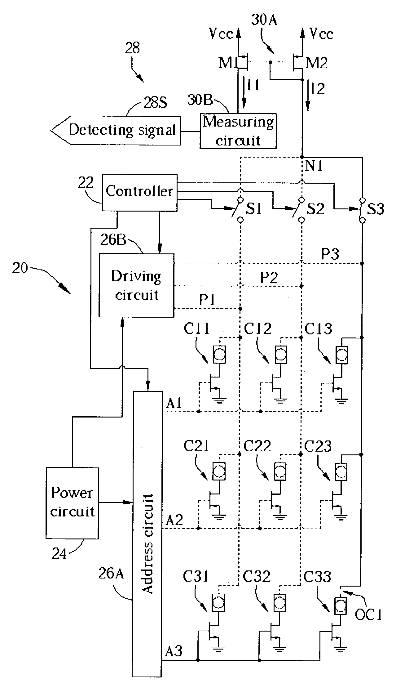
[0010]It is therefore a primary objective of the claimed invention to provide methods for detecting short-circuit and open-circuit problems of an inkjet printer. The short-circuit problem will not further damage the corresponding circuits of the printer during a short-circuit problem detecting process even if a short-circuit has appeared in the printer.
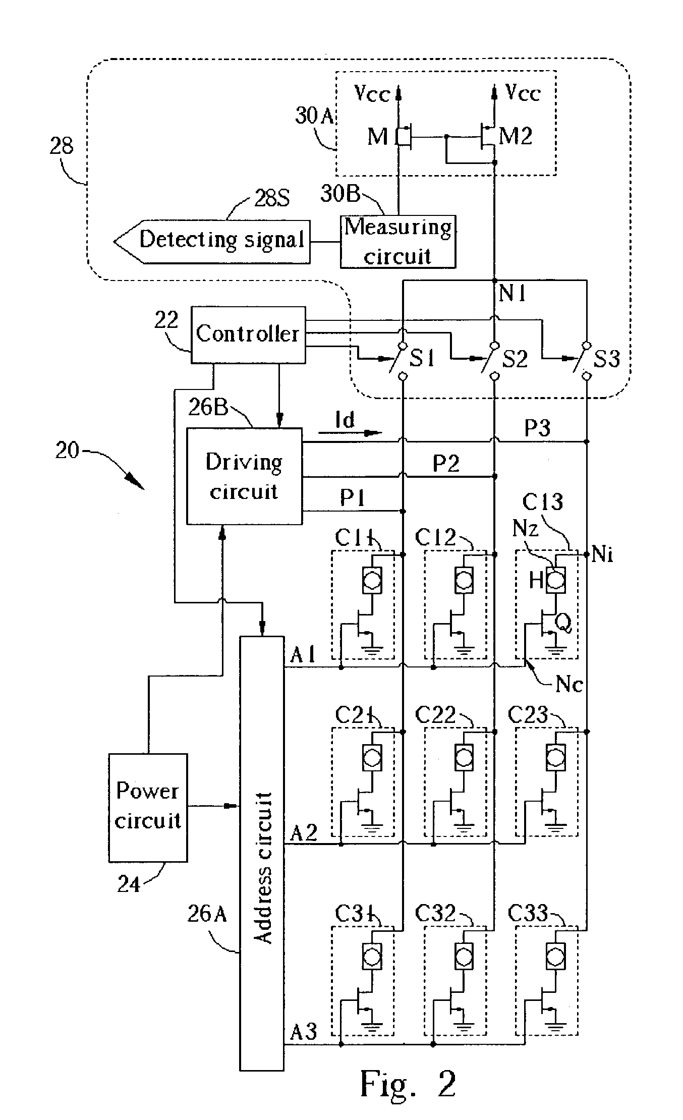
[0012]It is an advantage of the claimed invention that the claimed invention is capable of detecting the short-circuit problem and the open-circuit problem. When the printer is proceeding with the short-circuit detecting process, the driving circuit does not drive the driving lines even if the short-circuit problem already exists. Such a process will not further damage the driving circuit, power circuit, or any other important circuits of the printer. When the printer is proceeding with the open-circuit detecting process, the controller is capable of detecting what ink jet unit has open-circuit problems, what resistor is useless, or what switch of the printer has malfunctioned.

Problems solved by technology

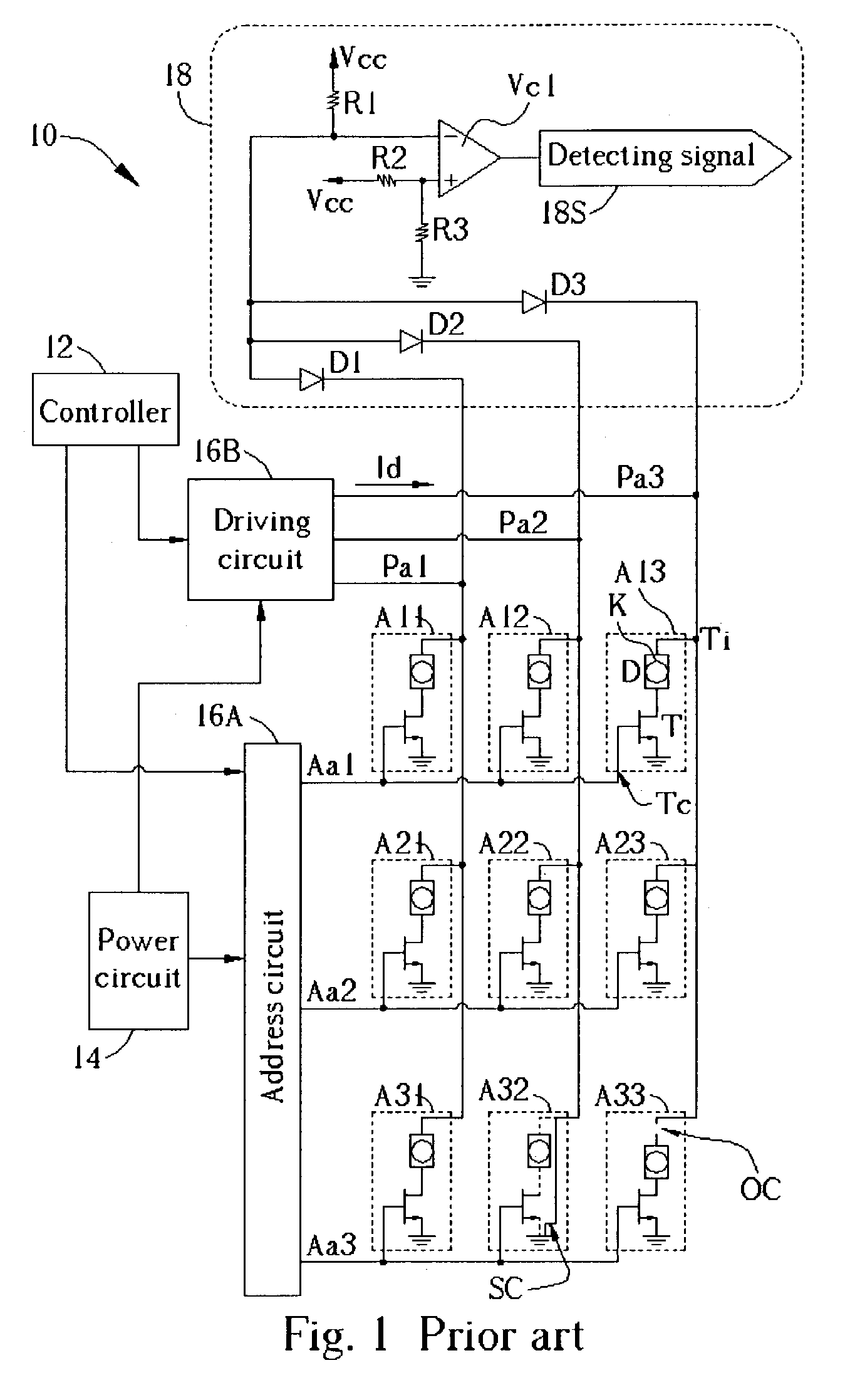
However, the printer 10 usually has some circuit problems.
That is, the printer 10 is not capable of effectively controlling the functionality of the ink jet unit A33.
The extremely high current may damage the control logic circuit of the driving circuit 16B or may further damage the power circuit 14.
Thus far the printer 10 is useless.

Method used


Image

  • Method and related apparatus for performing short and open circuit testing of ink jet printer head
  • Method and related apparatus for performing short and open circuit testing of ink jet printer head
  • Method and related apparatus for performing short and open circuit testing of ink jet printer head

Examples


Embodiment Construction

[0019]Please refer to FIG. 2, which is a schematic diagram of a circuit of a printer 20 according to the present invention. The printer 20 comprises a plurality of ink jet units C11 to C13, C21 to C23, and C31 to C33 disposed in matrix. The printer 20 further comprises a controller 22 for controlling the functionality of the printer 20, a power circuit 24 for providing energy to the ink jet units, an address circuit 26A for selectively controlling the ink jet units, a driving circuit 26B for selectively driving the ink jet units, and a detecting circuit 28 for detecting an open-circuit problem and a short-circuit problem. As each ink jet unit has the same structure, the ink jet unit C13 is described as an example. The ink jet unit C13 comprises a field effect transistor Q, a heating element H, and a corresponding nozzle Nz. A gate electrode Nc of the transistor Q serves as a control end of the ink jet unit C13. A source electrode of the ink jet unit C13 and a drain electrode of the ...


PUM


Abstract

Methods for detecting a short-circuit problem and an open-circuit problem in an ink jet printer. The ink jet printer includes at least an ink jet unit having an input end, a corresponding nozzle, and a control end. The ink jet printer further includes a driving circuit for providing energy to the ink jet unit via the input end. When the ink jet unit receives an ink jet signal via the control end, the ink jet unit can spray ink via the corresponding nozzle according to the energy received via the input end. The short-circuit problem detecting method includes stopping transmitting the ink jet signal to the control end of the ink jet unit, stopping providing energy to the input end of the ink jet unit, and measuring currents flowing through the input end of the ink jet unit.

Description

BACKGROUND OF INVENTION[0001]1. Field of the Invention[0002]The present invention relates to an ink jet printer, and more particularly, to a method and related apparatus for detecting short-circuit and open-circuit problems of inkjet units of the inkjet printer.[0003]2. Description of the Prior Art[0004]Having advantages of low-cost and excellent printing performance, ink jet printers have become one of the most popular electrical output devices.[0005]Please refer to FIG. 1, which is a schematic diagram of a circuit of a prior art printer 10 (U.S. Pat. No. 5,736,997). The printer 10 comprises a plurality of ink jet units A11 to A13, A21 to A23, and A31 to A33 disposed in matrix. The printer 10 further comprises a controller 12 for controlling the functionality of the printer 10, a power circuit 14 for providing energy to the ink jet units, an address circuit 16A for selectively controlling the ink jet units, a driving circuit 16B for selectively driving the ink jet units, and a dete...

Claims


Application Information

Patent Timeline
Patent Type & Authority Patents(United States)
IPC IPC(8): B41J29/393B41J2/05
CPCB41J2/0458B41J2/0451
Inventor CHEN, CHI-LUNHUNG, HAO-FENGHUANG, YAO-DE
Owner BENQ CORP
Learn More