
System and method for monitoring the performance of an inert gas distribution system

a technology of inert gas and distribution system, which is applied in the direction of liquid transfer device, process and machine control, specific gravity measurement, etc., can solve the problems of negating the value of the monitoring system, negating the value of the current oxygen sensor technology, and inability to meet the needs of hydrocarbons, etc., to achieve easy maintenance, reduce false readings or measurements, and easy verification

Active Publication Date: 2006-03-21
PARKER INTANGIBLES LLC
View PDF11 Cites 41 Cited by
  • Summary
  • Abstract
  • Description
  • Claims
  • Application Information

AI Technical Summary

Benefits of technology

"The present invention is a gas monitoring system for an inert gas generating system. The system includes a gas line, an oxygen sensor, a filter, a pump, a indicator, and a controller. The gas line is connected to the space to be inerted and has a first isolation valve to open or close the gas line to the atmosphere. The oxygen sensor is connected to the gas line and measures the oxygen concentration in the gas. A second isolation valve is opened or closed to discharge the gas to the space. The oxygen sensor can be verified before measuring the oxygen concentration. The system monitors the inert gas system by measuring the oxygen concentration in the space instead of inferring it from the inert gas generating system output. The oxygen sensor is standard and cost-effective. The system can be easily mounted and maintained. The oxygen concentration is measured directly and not inferred. The invention provides a more efficient, reliable, cost-effective, and safe gas monitoring system."

Problems solved by technology

This inferred oxygen concentration is often inaccurate or incorrect, thereby negating any value that the monitoring system may have.
Furthermore, current oxygen sensor technology is incompatible with hydrocarbons and, therefore, generally cannot be placed directly into a fuel tank.
This is because current oxygen sensors operate at elevated temperatures, which presents a serious explosion risk within the fuel tank.

Method used


Image

  • System and method for monitoring the performance of an inert gas distribution system
  • System and method for monitoring the performance of an inert gas distribution system
  • System and method for monitoring the performance of an inert gas distribution system

Examples


Embodiment Construction

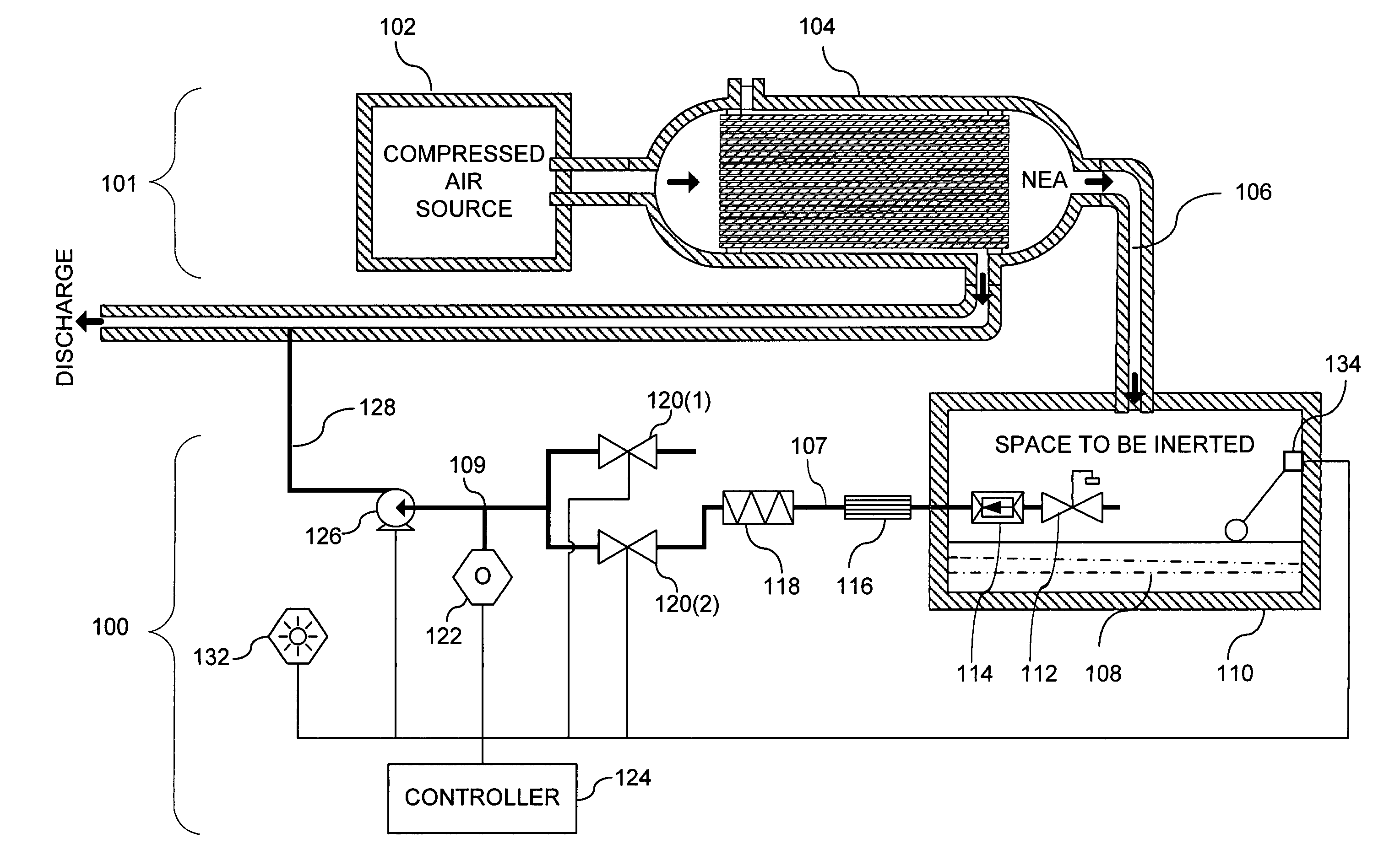
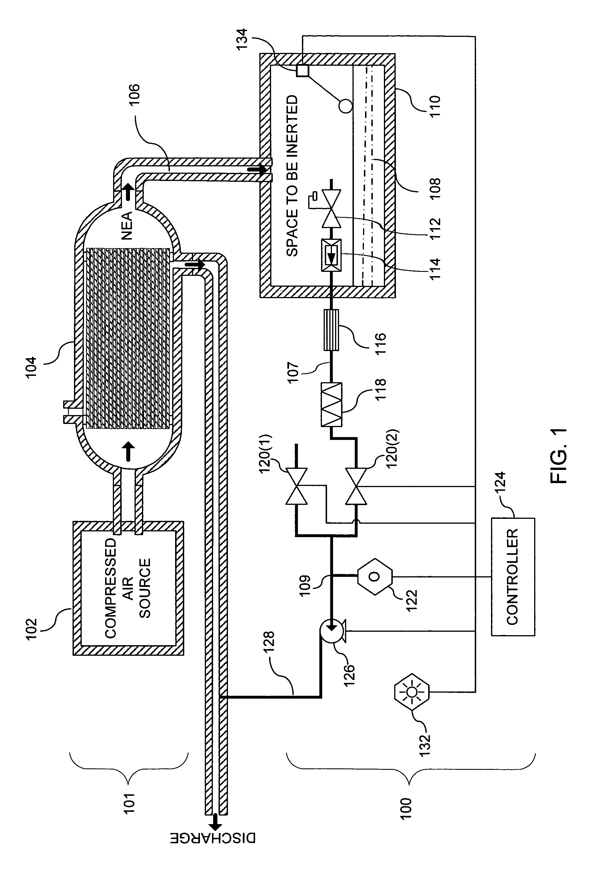
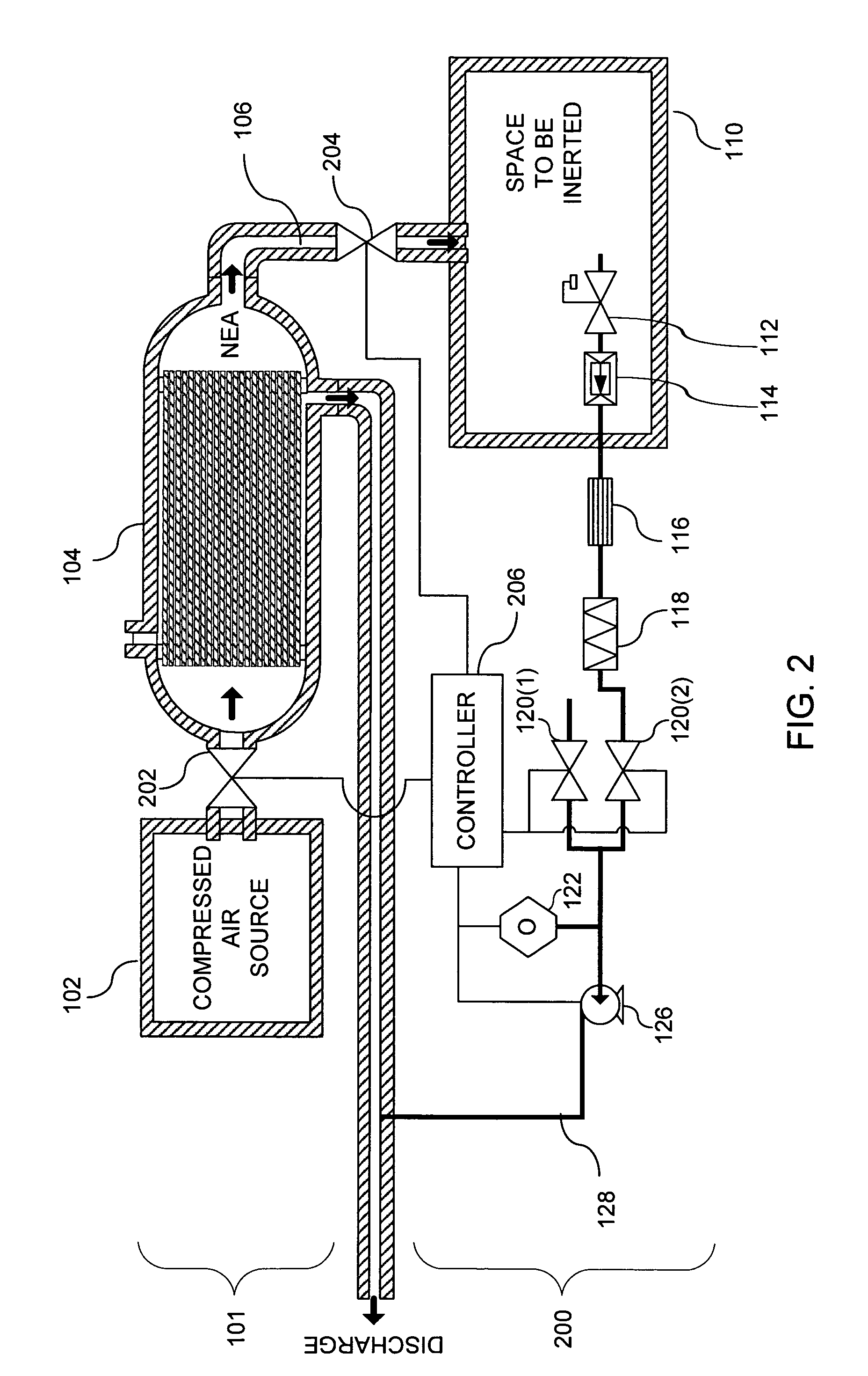
[0026]FIG. 1 is a schematic view of a gas monitoring system 100. The gas monitoring system 100 monitors and in some embodiments controls an inert gas system 101. Inert gas generating systems are typically used to inject nitrogen or other inert gasses into the ullage of fuel tanks and / or cargo spaces of aircraft. This inert gas displaces and / or mixes with the gas currently in the space, thereby lowering the oxygen concentration of gas in the space and inerting the gas within the space to reduce explosion hazards.

[0027]The inert gas system 101 may be any system for generating and / or distributing inert gas. For ease of explanation, FIG. 1 shows an example of an inert gas system 101 that includes a source of compressed air 102 and an air separation module (ASM) 104. The source of compressed air 102 may be aircraft engine bleed air, which is typically supplied from taps in the turbine section of the aircraft engines at temperatures in the range of 300 degree F.–400 degree F. and at press...


PUM


Abstract

The gas monitoring system may include a gas line, an oxygen sensor, a filter, a pump, a indicator, and a controller. The gas line is configured to convey gas from a space configured to receive inert gas to a location remote from the space. The oxygen sensor is fluidly coupled to the gas line at the location. The oxygen sensor is configured to determine a partial pressure of oxygen present in the gas. The filter is fluidly coupled to the gas line between the space and the location. The filter is configured to remove combustible contaminants from the gas before it reaches the oxygen sensor. The controller is electrically coupled to the oxygen sensor and to the indicator. The controller is configured to activate the indicator when the partial pressure of oxygen exceeds a predetermined level.

Description

BACKGROUND OF THE INVENTION[0001]1. Field of the Invention[0002]The invention relates generally to inert gas distribution systems, such as those used on aircraft. More specifically, the invention relates to a system and method for monitoring and / or controlling an inert gas distribution system.[0003]2. Description of the Related Art[0004]The energy requirements of most modern aircraft are supplied by combusting aviation gasoline, which is typically stored in fuel tanks within an aircraft's wings. Such fuel tanks also contain an explosive fuel / oxygen mixture in the area above the fuel, otherwise known as the ullage. Accordingly, many systems have been developed to reduce the danger of accidentally igniting this fuel / oxygen mixture.[0005]One way of addressing such a danger is to replace the explosive fuel / oxygen mixture with a nonflammable inert gas, usually nitrogen. One method to accomplish this is the On-board Inert Gas Generating System (OBIGGS), which separates nitrogen from local...

Claims


Application Information

Patent Timeline
Patent Type & Authority Patents(United States)
IPC IPC(8): F04F1/00B67D7/72G05D7/00G05D11/13
CPCG05D11/138Y10T137/8242Y10T137/8158Y10T137/3127Y10T137/8326Y10T137/0379
Inventor JONES, PHILIP E.O'HARA, MICHAEL J.GREENAWALT, BRIAN P.
Owner PARKER INTANGIBLES LLC
Learn More