
Heating resistor type flow-measuring device having a heating resistor and a thermoresistance, whose resistance value varies in response to the ambient temperature

a flow-measuring device and heating resistor technology, which is applied in the direction of heat measurement, liquid/fluent solid measurement, instruments, etc., can solve the problems of cumbersome initial adjustment of heating resistor, difficult to adjust heating temperature properly according, and large weight of heating resistor-type flow-measuring devi

Active Publication Date: 2006-03-14
HITACHI ASTEMO LTD
View PDF11 Cites 33 Cited by
  • Summary
  • Abstract
  • Description
  • Claims
  • Application Information

AI Technical Summary

Benefits of technology

This configuration results in a small-sized and lightweight heating resistor type flow-measuring device capable of adjusting heating temperature according to ambient conditions and facilitating initial adjustments, maintaining precision without the need for large MOS transistors or increased chip size.

Problems solved by technology

However, with the technology disclosed in the patent document 1, the initial adjustment of the heating resistor is cumbersome and requires a lot of time, and in addition, after the initial adjustment of the heating resistor, it is difficult to alter the heating temperature properly according to a change in the ambient temperature.
However, for this purpose, the sizes of the MOS transistors 48, 49, 50, 51, 52 need to be increased, and consequently the heating resistor type flow-measuring device becomes large and heavy in weight.
In the case where this variable resistor circuit is implemented in an integrated circuit, extremely large chip size is required.
Because of this, it is difficult to attain small size and lightweight and to adjust the heating temperature of the heating resistor according to the ambient temperature as well as making the initial adjustment.

Method used


Image

  • Heating resistor type flow-measuring device having a heating resistor and a thermoresistance, whose resistance value varies in response to the ambient temperature
  • Heating resistor type flow-measuring device having a heating resistor and a thermoresistance, whose resistance value varies in response to the ambient temperature
  • Heating resistor type flow-measuring device having a heating resistor and a thermoresistance, whose resistance value varies in response to the ambient temperature

Examples


Embodiment Construction

[0026]Hereafter, a preferred embodiment of the present invention will be described referring to the accompanying drawings.

[0027]Note that an example that will be described below is an example in which the present invention is applied to an air flowmeter.

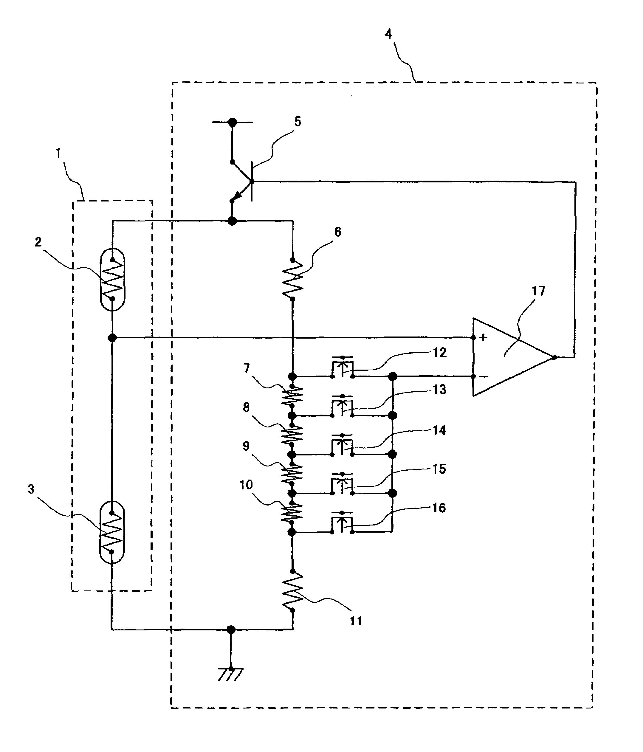
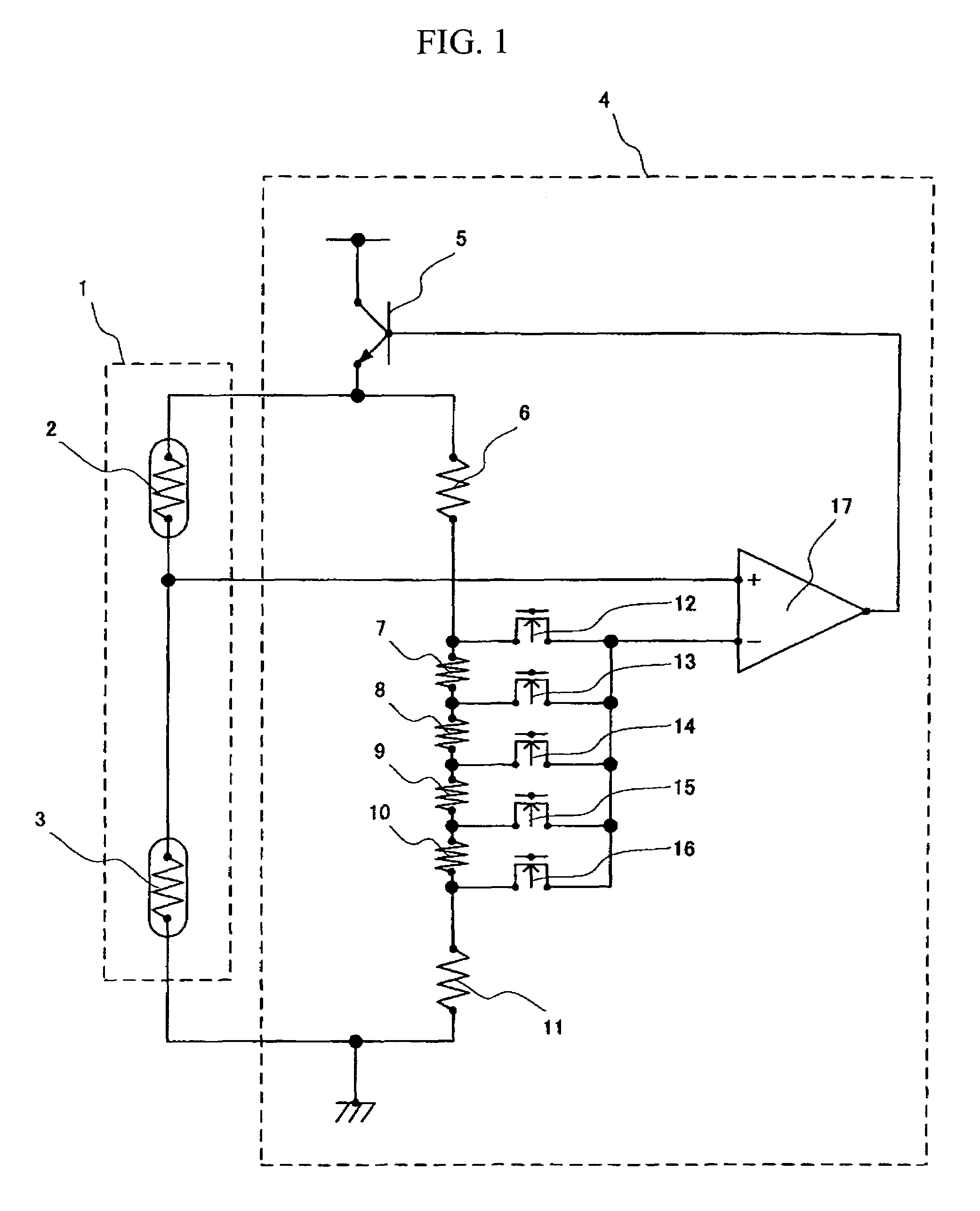
[0028]First of all, an air flowmeter that is the first embodiment of the present invention will be described referring to FIGS. 1 to 5. FIG. 1 is a sectional view of the drive circuit of a heating resistor 2 of the air flowmeter that is the first embodiment, FIG. 2 is a plan view of a sensor element 1 of the air flowmeter of the first embodiment, and FIG. 3 is a sectional view of the sensor element 1 of the air flowmeter of the first embodiment taken along with line A–A′ of FIG. 2.

[0029]First, a configuration of the sensor element 1 of the air flowmeter shown in FIG. 1 will be described referring to FIGS. 2 and 3.

[0030]In FIG. 2 and FIG. 3, the sensor element 1 has a planar substrate 18 made of a material of excellent thermal conduct...


PUM

PropertyMeasurementUnit
temperatureaaaaaaaaaa
resistanceaaaaaaaaaa
temperatureaaaaaaaaaa

Abstract

A heating resistor type flow-measuring device is capable of adjusting heating temperature of a heating resistor according to the ambient temperature as well as making the initial adjustment. A heating resistor, a thermoresistance, a group of the resistors, and an amplifier constitute a bridge circuit, and leading terminals of the group of resistors are connected to one of input terminals of an amplifier for amplifying an error voltage through MOS transistors. The heating temperature of the heating resistor can be changed by selecting one of the MOS transistors and turning it on.

Description

FIELD OF THE INVENTION[0001]The present invention relates to a heating resistor type flow-measuring device and more particularly to a heating resistor type flow-measuring device capable of easily adjusting the temperature of a heating resistor based on digital information.BACKGROUND OF THE INVENTION[0002]There is an air flowmeter as an example of the heating resistor type flow-measuring device. This air flowmeter comprises: a heating resistor (heater); a current control circuit (feedback control using a bridge circuit) for maintaining the temperature of this heating resistor to a constant temperature; a temperature sensor disposed near the heating resistor, and a thermoresistance whose resistance value changes in response to the ambient temperature (a flow sensor described in the patent document 1, and a heater drive circuit described in the patent document 2).[Patent document 1] JP-A No. 310762 / 2002[Patent document 2] JP-A No. 314645 / 2000[0003]Generally, in the heating resistor typ...

Claims


Application Information

Patent Timeline
Patent Type & Authority Patents(United States)
IPC IPC(8): G01F1/68G01F1/698G01F1/684G01F1/692G01F1/696G01F1/699G01K7/20
CPCG01F1/6845G01K7/20G01F1/699G01F1/692
Inventor MATSUMOTO, MASAHIROYAMADA, MASAMICHINAKANO, HIROSHIWATANABE, IZUMIHANZAWA, KEIJISATO, RYO
Owner HITACHI ASTEMO LTD
Learn More