
Construction machine management system, and construction machine

a management system and construction machine technology, applied in the field of construction machines, can solve the problems of affecting the service life of the machine, so as to reduce the cost of communication

Inactive Publication Date: 2006-03-07
NIHON KENKI CO LTD
View PDF32 Cites 4 Cited by
  • Summary
  • Abstract
  • Description
  • Claims
  • Application Information

AI Technical Summary

Benefits of technology

The present invention provides a construction machine management system that reduces communication cost by transmitting construction machine location information only when required, and without causing any inconvenience to the party supplied or provided with the construction machine. The system includes a location detector, a determination device, and a transmitter. The location information can be transmitted to a base station for analysis and comparison with previous location information to detect abnormalities that may indicate theft or other danger. The determination result can be transmitted to a managing division or user of the construction machine using electronic mail or the like. Overall, the system helps to reduce communication costs and improve safety on construction sites.

Problems solved by technology

By transmitting the information regularly as described above, it is uneconomical because transmission costs may be increased needlessly.
Upon completion of work, it is common to leave the construction machine behind at that remote location because it is too troublesome to collect the machine using a transport vehicle.
Under these conditions, management of the construction machine by a manager is compromised, which places a mental strain on the manager.
For example, in the event that the construction machine breaks down, the location of the broken down machine is confirmed through contact from the person being supplied or provided with the construction machine, and a serviceman will only be called out after confirmation, which takes some time and delays the machine being put back in to service.

Method used


Image

  • Construction machine management system, and construction machine
  • Construction machine management system, and construction machine
  • Construction machine management system, and construction machine

Examples


first embodiment -

[0026]-First Embodiment-

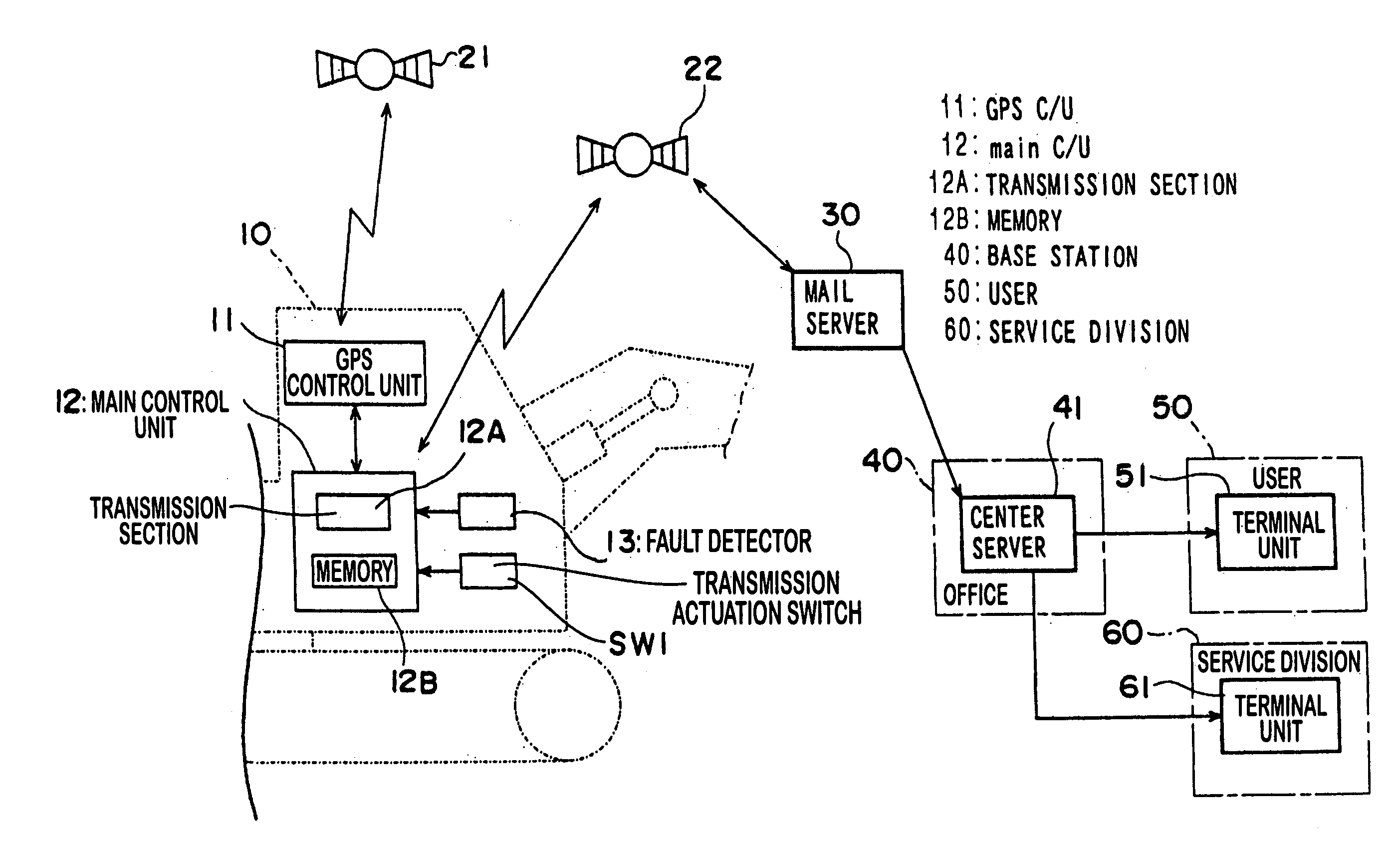
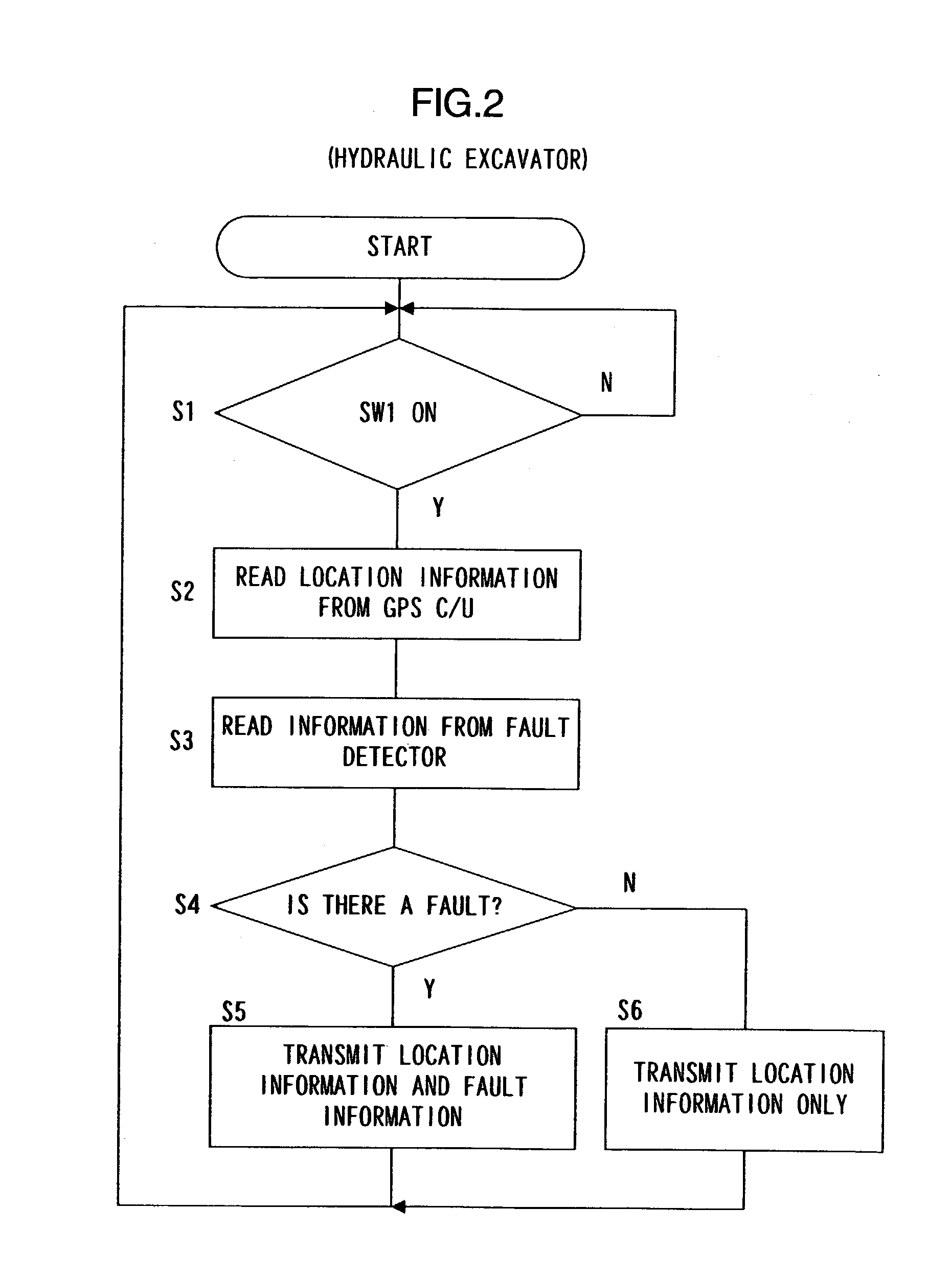
[0027]An embodiment of a management system according to the present invention will now be described by applying it to a hydraulic excavator, using FIG. 1 to FIG. 3.

[0028]FIG. 1 is a schematic diagram of a system of the present invention. GPS control units 11 mounted separately in each hydraulic excavator 10 receive radio signals from a plurality of GPS satellites 21 and calculate location information for each hydraulic excavator 10 (in which they are mounted). The calculated location information is input to a main control unit 12. The location information here is, for example, geographical information (latitude and longitude). A transmission actuation switch SW1 provided in the operator's cabin and a fault detector 13 for detecting faults with the hydraulic excavator 10 are also connected to the main control unit 12. The transmission actuation switch SW1 is a switch actuated by the operator when wishing to transmit location information. The fault detector 13 ...

second embodiment -

[0041]-Second Embodiment-

[0042]A second embodiment of the present invention will now be described using FIG. 4 to FIG. 7.

[0043]With this embodiment, it is determined that there is a danger that the hydraulic excavator 10 has been stolen if locations of the hydraulic excavator 10 are different at the point in time the engine of the hydraulic excavator 10 was turned off and the point in time it is turned on again, and the location information at the engine start-up time point is transmitted. The system structure is identical with FIG. 1.

[0044]FIG. 4 shows processing in the main control unit 12 of the hydraulic excavator 10 when the engine is stopped. In step S31, if it is determined that the engine has been stopped, for example from an engine key off signal, location information at that time point is read in from the GPS control unit 11 (step S32). Then the location information thus read in is stored in the memory 12B as location information P1 (step S33). Therefore, when the engine i...

third embodiment -

[0050]-Third Embodiment-

[0051]A third embodiment of the present invention will now be described using FIG. 8 to FIG. 11. This embodiment, similarly to the second embodiment, is also intended to prevent theft of the hydraulic excavator 10.

[0052]FIG. 8 is a schematic diagram of this embodiment, and structural elements that are the same as those in FIG. 1 have the same reference numerals attached thereto. A center server 41 of the base station 40 is capable of transmitting information as required to a terminal unit 71 of a construction machine rental company 70 via communications line such as a telephone line, using electronic mail or the like. Information communication is also possible between the terminal 71 of the rental company 70 and a terminal 51 of a user 50 using the construction machine of the rental company 70. The remaining structure is the same as in FIG. 1.

[0053]A base station 40 being one of the managing division for the construction machine, performs a service for a user...


PUM


Abstract

A construction machine comprises a location detector for detecting location information for the construction machine, a determination device for determining whether or not location information is to be transmitted and outputting a transmission signal if it is determined that information is to be transmitted, and a transmitter for transmitting the detected location information to a base station in response to the transmission signal.

Description

TECHNICAL FIELD[0001]The present invention relates to a construction machine capable of transmitting location information to a base station, and to a management system using this construction machine.BACKGROUND ART[0002]Systems for managing traveling conditions of vehicles such as cars, dump trucks etc. have been disclosed in, for example, Japanese Laid-open Patent Publication No. H4-174387 and Japanese Laid-open Patent Publication No. H4-174388. With the systems disclosed in these patent publications, location information of individual vehicles is detected using a GPS satellite, and that location information is regularly transmitted to a base station. However, it is not always necessary to keep current location information at the base station, depending on the intended use for the location information. By transmitting the information regularly as described above, it is uneconomical because transmission costs may be increased needlessly.[0003]The systems disclosed in the above publi...

Claims


Application Information

Patent Timeline
Patent Type & Authority Patents(United States)
IPC IPC(8): G06F19/00G06F7/70E02F9/20G08G1/123
CPCE02F9/2025G08G1/20E02F9/2045E02F9/26E02F9/267E02F9/20
Inventor ADACHI, HIROYUKIHIRATA, TOICHISUGIYAMA, GENROKUWATANABE, HIROSHISHIBATA, KOICHIKOMATSU, HIDEKI
Owner NIHON KENKI CO LTD
Learn More