DC-DC converter circuits and method for reducing DC bus capacitor current
a converter circuit and current reduction technology, applied in the direction of electric variable regulation, process and machine control, instruments, etc., can solve the problem of relatively high capacitor cost and achieve the effect of reducing heat loss
- Summary
- Abstract
- Description
- Claims
- Application Information
AI Technical Summary
Benefits of technology
Problems solved by technology
Method used
Image
Examples
Embodiment Construction
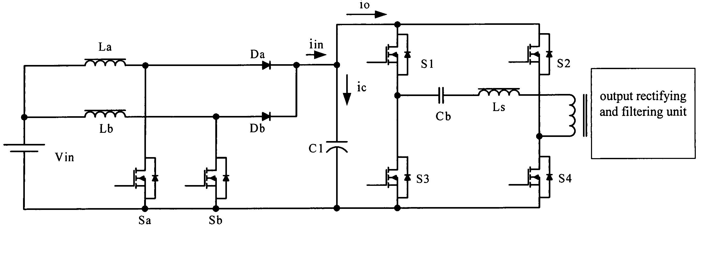
[0035]To decrease the DC Bus capacitor current, the present invention improves the topology design of the multi-stage converter. The main circuit configuration having the double-frequency PFC circuit in the front-end and the phase-shifted full-bridge DC-DC converter in the back-end is proposed in the present invention as shown in FIG. 4. In which, the back-end of the system employs the same circuit as shown in FIG. 1, the main difference between the two is that the PFC circuit in the front-end is improved from a single configuration to the dual configuration. In FIG. 4, the Vin, the inductors La and Lb, the power switches Sa and Sb, the power diodes Da and Db, and the DC Bus capacitor C1 constitute the PFC unit. The elements La, Sa, and Da correspond to the elements Lb, Sb, and Db, and each group respectively forms an independent unit. The main operational principles of the proposed circuit are: 1. There is a difference of 180 degrees between corresponding phase angles of the contro...
PUM
 Abstract
Description
Claims
Application Information
 - R&D
- Intellectual Property
- Life Sciences
- Materials
- Tech Scout
- Unparalleled Data Quality
- Higher Quality Content
- 60% Fewer Hallucinations
Browse by: Latest US Patents, China's latest patents, Technical Efficacy Thesaurus, Application Domain, Technology Topic, Popular Technical Reports.
© 2025 PatSnap. All rights reserved.Legal|Privacy policy|Modern Slavery Act Transparency Statement|Sitemap|About US| Contact US: help@patsnap.com


