
RFID communication system and the search method thereof

Inactive Publication Date: 2006-03-07
SUNPLUS TECH CO LTD
View PDF2 Cites 33 Cited by
  • Summary
  • Abstract
  • Description
  • Claims
  • Application Information

AI Technical Summary

Benefits of technology

[0011]An object of the present invention is to provide a radio frequency identification (RFID) communication system and the search method thereof, which can increase time efficiency.
[0012]Another object of the present invention is to provide a radio frequency identification (RFID) communication system and the search method thereof, which can reduce unnecessary communication and switch between a read and a plurality of transponders, reduce unnecessary guard time and shorten blank time of transmission.

Problems solved by technology

RFID communication system is increasing quickly and its applications become more diversified, thus typical one-to-one communication cannot meet existing applications.
However, such a solution is hard in design for a non-microwave system.
However, such a solution costs very high and is limited in specific applications.
However, such a solution has a poor performance when the number of transponders is large.
However, it wastes time and reduces entire performance.
However, applying the random number method may cause no response signal during a certain time, and both occurrence point and duration regarding the certain time are unpredictable, thus leading to poor time efficiency.

Method used


Image

  • RFID communication system and the search method thereof
  • RFID communication system and the search method thereof
  • RFID communication system and the search method thereof

Examples


Embodiment Construction

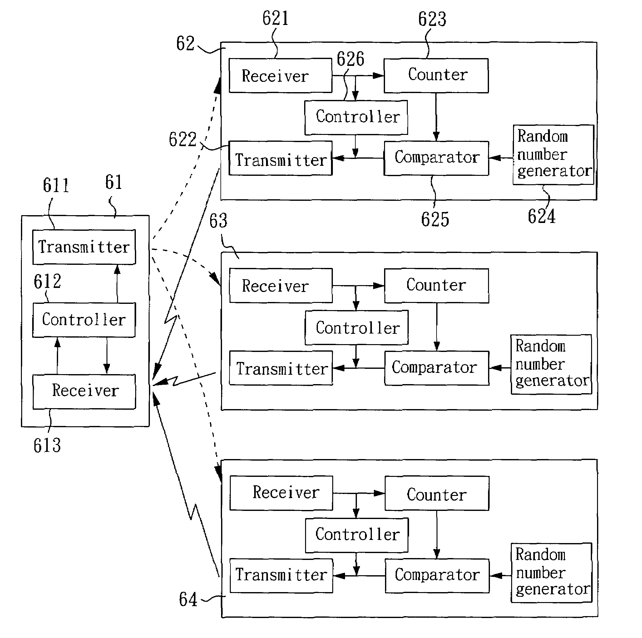
[0024]FIG. 6 is a schematic diagram of a system configuration in accordance with a preferred embodiment of the invention, where an example of personnel access control is given. In FIG. 6, the system consists of a reader 61 and three transponders 62–64. As shown in FIG. 6, the reader 61 has a transmitter 611, a controller 612 and a receiver 613. Each of the transponders 62–64 has a receiver 621, a transmitter 622, a counter 623, a random number generator 624, a comparator 625 and a controller 626.

[0025]In this embodiment, the reader 61 is implemented on important entrances and each of the transponders 62–64 represents a personal smart card with built-in data (e.g., employee number and certificate number) in an internal memory or represented by received voltage on an external pin. Therefore, personnel access control is achieved by applying the reader 61 to read built-in data of the transponders 62–64.

[0026]The reader 61 can detect a communication region so as to find the transponders ...


PUM


Abstract

A radio frequency identification (RFID) communication system and the search method thereof are disclosed, which apply search instructions and reads instructions to communicate between a read and a plurality of transponders. Each transponder generates a random number for comparison with received search instructions. When the random number meets with the number of received search instructions, a response request is sent by a corresponding transponder such that the reader can read the content of the corresponding transponder.

Description

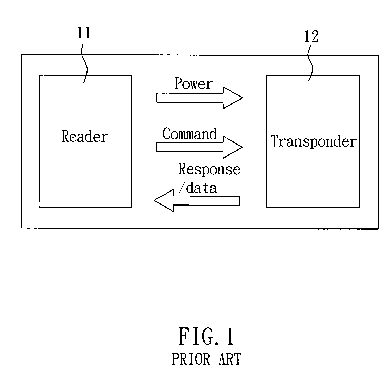
BACKGROUND OF THE INVENTION[0001]1. Field of the Invention[0002]The present invention relates to a radio frequency identification (RFID) communication system and, more particularly, to a radio frequency identification (RFID) communication system and the search method thereof.[0003]2. Description of Related Art[0004]FIG. 1 is a schematic diagram of essential devices of a typical RFID communication system. In FIG. 1, the system includes a reader 11 and a transponder 12. As shown in FIG. 1, the operation principle for the system is that the reader 11 sends a carrier with instructions to the transponder 12 and the transponder 12 obtains DC power via rectifying the carrier. Further, a demodulator inside the transponder demodulates instructions on the carrier, thereby responding the reader or sending required data according to the instructions demodulated.[0005]RFID communication system is increasing quickly and its applications become more diversified, thus typical one-to-one communicati...

Claims


Application Information

Patent Timeline
IPC IPC(8): G08B13/14G06K7/00H04Q5/22
CPCG06K7/10029G06K7/0008
Inventor LIAO, TUNG-TSAILEE, HSIN-CHOUCHEN, WU-SHIN
Owner SUNPLUS TECH CO LTD
Learn More