Pattern formation method and pattern formation apparatus, method for manufacturing device, electro-optical device, electronic device, and method for manufacturing active matrix substrate

a pattern formation apparatus and pattern formation technology, applied in the direction of conductive pattern formation, identification means, instruments, etc., can solve the problems of increasing the cost of such banks as described above, not being able to achieve sufficient accuracy with regard to line width, and liquid drops that are not sufficiently wet and spread ou

Inactive Publication Date: 2006-03-07
SEIKO EPSON CORP
View PDF6 Cites 9 Cited by
  • Summary
  • Abstract
  • Description
  • Claims
  • Application Information

AI Technical Summary

Benefits of technology

[0008]The present invention has been conceived in the light of the above described situation, and it takes as its object the provision of a pattern formation method and pattern formation apparatus, and of a method for manufacturing a device, which, when forming a film pattern such as a wiring pattern or the like by using a liquid drop ejection method, can dispose the liquid drops smoothly even at the end portions of groove portions between banks, and can thus form a film pattern having a desired pattern configuration. Furthermore, the present invention takes as its object the provision of an electro-optical device, of an electronic device, and of a method for manufacturing an active matrix substrate, which have a film pattern which has been formed in a desired pattern configuration.

Problems solved by technology

However, in recent years, increase in density of the circuitry of such devices has progressed remarkably, and, although there are ongoing insistent demands for further progress in the fineness of the wiring of wiring patterns and the further miniaturization thereof, nevertheless, when attempts have been made to produce such minute wiring patterns, it has been difficult, in particular, to attain sufficient accuracy with regard to their line width.
However, when thus disposing the liquid drops in the groove portions formed between these banks, it has become apparent that sometimes it happens that the liquid drops do not sufficiently wet and spread out, in particular at the end portions of the groove portions.
On the other hand, it is possible that the provision of such banks as described above may entail an increase in cost, since they are manufactured by utilizing a photolithographic method.

Method used


Image

  • Pattern formation method and pattern formation apparatus, method for manufacturing device, electro-optical device, electronic device, and method for manufacturing active matrix substrate
  • Pattern formation method and pattern formation apparatus, method for manufacturing device, electro-optical device, electronic device, and method for manufacturing active matrix substrate
  • Pattern formation method and pattern formation apparatus, method for manufacturing device, electro-optical device, electronic device, and method for manufacturing active matrix substrate

Examples


first preferred embodiment

Pattern Formation Method

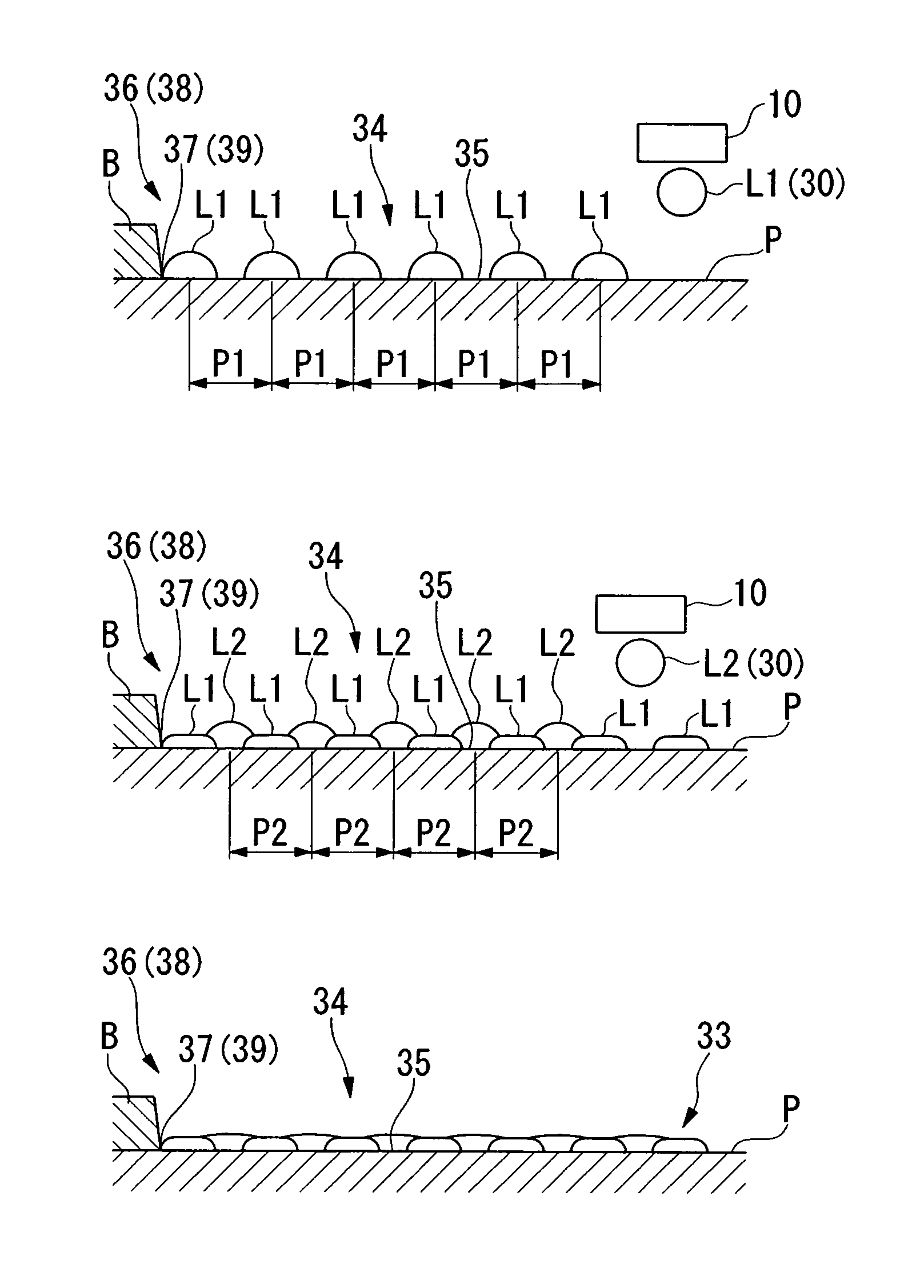
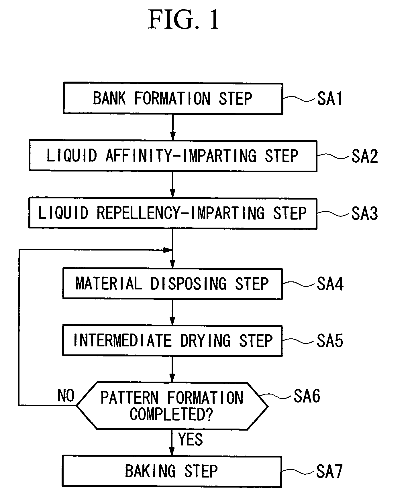
[0072]In the following, a first preferred embodiment of the pattern formation method according to the present invention will be explained with reference to the drawings. FIG. 1 is a flow chart showing the first preferred embodiment of the pattern formation method according to the present invention.

[0073]Here, for this first preferred embodiment of the present invention, an example will be explained in which an electrically conductive film wiring pattern is formed upon a glass substrate. Furthermore, as the functional liquid for making this electrically conductive film wiring pattern, there is used an organic silver compound dissolved in diethylene glycol diethyl ether solvent (a dispersion medium).

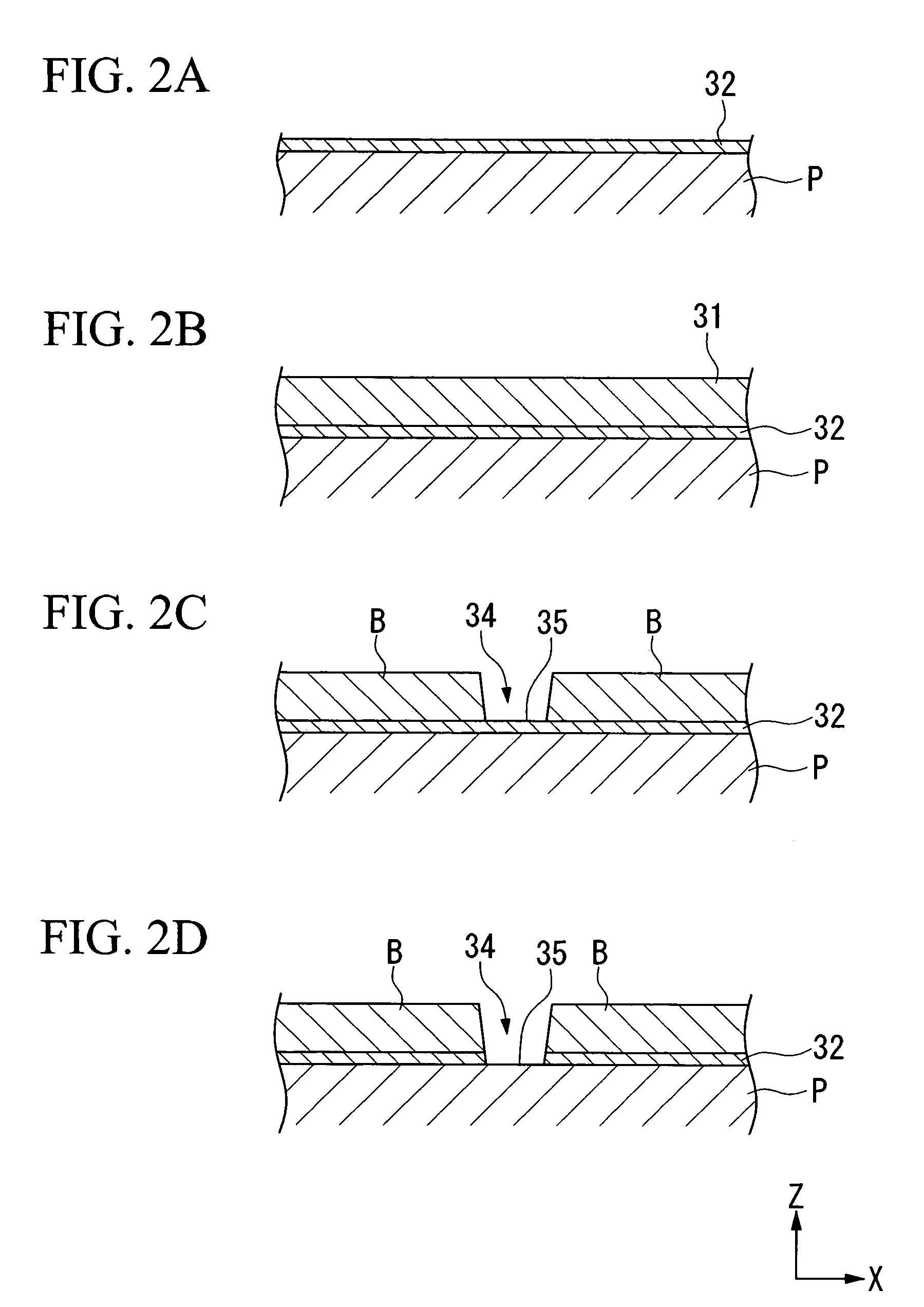
[0074]Referring to FIG. 1, the pattern formation method according to this first preferred embodiment of the present invention includes: a bank formation step in which liquid drops of a functional liquid are disposed upon the substrate so as to form banks which corre...

second preferred embodiment

Pattern Formation Method

[0115]In the following, a preferred embodiment of the pattern formation method according to the present invention will be explained with reference to the figures. FIG. 9 is a flow chart showing this preferred embodiment of the pattern formation method according to the present invention.

[0116]Here, for this second preferred embodiment of the present invention, an example will be explained in which an electrically conductive film wiring pattern is formed upon a glass substrate. Furthermore, as the functional liquid for making this electrically conductive film wiring pattern, there is used an organic silver compound dissolved in diethylene glycol diethyl ether solvent (a dispersion medium).

[0117]Referring to FIG. 9, the pattern formation method according to this second preferred embodiment of the present invention includes: a substrate cleaning step in which the substrate upon which the liquid drops of a functional liquid are to be disposed is cleaned using a pr...


PUM

PropertyMeasurementUnit
temperatureaaaaaaaaaa
contact angleaaaaaaaaaa
speedaaaaaaaaaa

Abstract

A pattern formation method for forming a film pattern upon a substrate, including the steps of: forming banks in a predetermined pattern upon the substrate; disposing liquid drops of a functional liquid at the end portions of groove portions which are defined between the banks; and after having disposed the drops at the end portions of the groove portions, disposing liquid drops in positions of the groove portions other than the end portions thereof.

Description

BACKGROUND OF THE INVENTION[0001]1. Field of the Invention[0002]Priority is claimed on Japanese Patent Application No. 2004-95976, filed Mar. 29, 2004, the content of which is incorporated herein by reference.[0003]The present invention relates to a pattern formation method and pattern formation apparatus, to a method for manufacturing a device, to an electro-optical device, to an electronic device, which form a film pattern by disposing liquid drops of a functional liquid upon a substrate.[0004]2. Description of Related Art[0005]From the past, as methods of manufacturing devices which have very fine wiring patterns (film patterns), such as semiconductor integrated circuits and the like, although many photolithographic methods have been used, attention has also been paid to methods of manufacturing such devices using liquid drop ejection methods. Such liquid drop ejection methods exhibit the beneficial features that the useless consumption of functional liquid is minimized, and that...

Claims


Application Information

Patent Timeline
Patent Type & Authority Patents(United States)
IPC IPC(8): H01L21/00G02F1/1343B05D1/26G02F1/1345G02F1/1368G09F9/00H01L21/28H01L21/288H01L21/3205H01L21/336H01L29/786H01L51/40H01L51/50H01L51/56H05B33/10H05B33/12H05K3/12
CPCB82Y30/00H01L51/0004H05K3/1241H10K71/13
Inventor HASEI, HIRONORI
Owner SEIKO EPSON CORP
Why Eureka
Try Eureka