Needleless injection site

a needleless injection and needle technology, applied in the field of medical arts, can solve the problems of affecting the overall utility of the injection site,

Inactive Publication Date: 2006-03-07
BECTON DICKINSON & CO
View PDF79 Cites 29 Cited by
  • Summary
  • Abstract
  • Description
  • Claims
  • Application Information

AI Technical Summary

Benefits of technology

[0018]In the first embodiment, the distal portion of the dilator projection has a tapered outer surface for facilitating the connection of the adapter member and hence the housing to a tubular fluid line. In particular, the housing is connected to the fluid line via the insertion of the distal portion of the dilator projection into the lumen of the fluid line, with the distal portion being frictionally retained within the lumen subsequent to being inserted thereinto.
[0019]The adapter member further comprises a tubular adapter sleeve which is slidably extensible over and frictionally maintainable on the distal portion of the dilator projection for facilitating the connection of the housing to a Luer connector. The housing is connected to the Luer connector via the insertion of the adapter sleeve into the lumen of the Luer connector. The distal portion of the dilator projection preferably has a tapered outer surface, with the adapter sleeve preferably having a tapered bore extending longitudinally therethrough which is complimentary to the outer surface of the distal portion of the dilator projection, thus facilitating the frictional retention of the adapter sleeve thereon. Additionally, the distal portion of the dilator projection preferably includes an elongate rib formed on the outer surface thereof, with the bore of the adapter sleeve defining an elongate slot therewithin which is sized and configured to receive the rib when the adapter sleeve is slidably advanced over the distal portion of the dilator projection. The receipt of the rib into the slot is operable to prevent the rotation of the adapter sleeve upon the distal portion of the dilator projection. Further, the adapter sleeve preferably has a tapered outer surface for frictionally retaining the adapter sleeve within the lumen of the Luer connector subsequent to being inserted thereinto.

Problems solved by technology

However, the necessity of having to utilize a syringe with a needle to facilitate the introduction of the medication into the solution flow is undesirable due to the risk of inadvertent needle sticks.
Though these needleless injection sites eliminate the need of having to puncture the diaphragm with a needle, they also possess certain deficiencies which detract from their overall utility.
Foremost of these deficiencies is the difficulty associated with disinfecting the injection site, and, in particular the diaphragm thereof, subsequent to medication being infused thereinto.
However, due to the configuration of the diaphragm, complete and effective disinfection thereof is often difficult to achieve, thus increasing the risk of the introduction of contaminates into the solution stream upon subsequent uses of the injection site.

Method used


Image

  • Needleless injection site
  • Needleless injection site
  • Needleless injection site

Examples


second embodiment

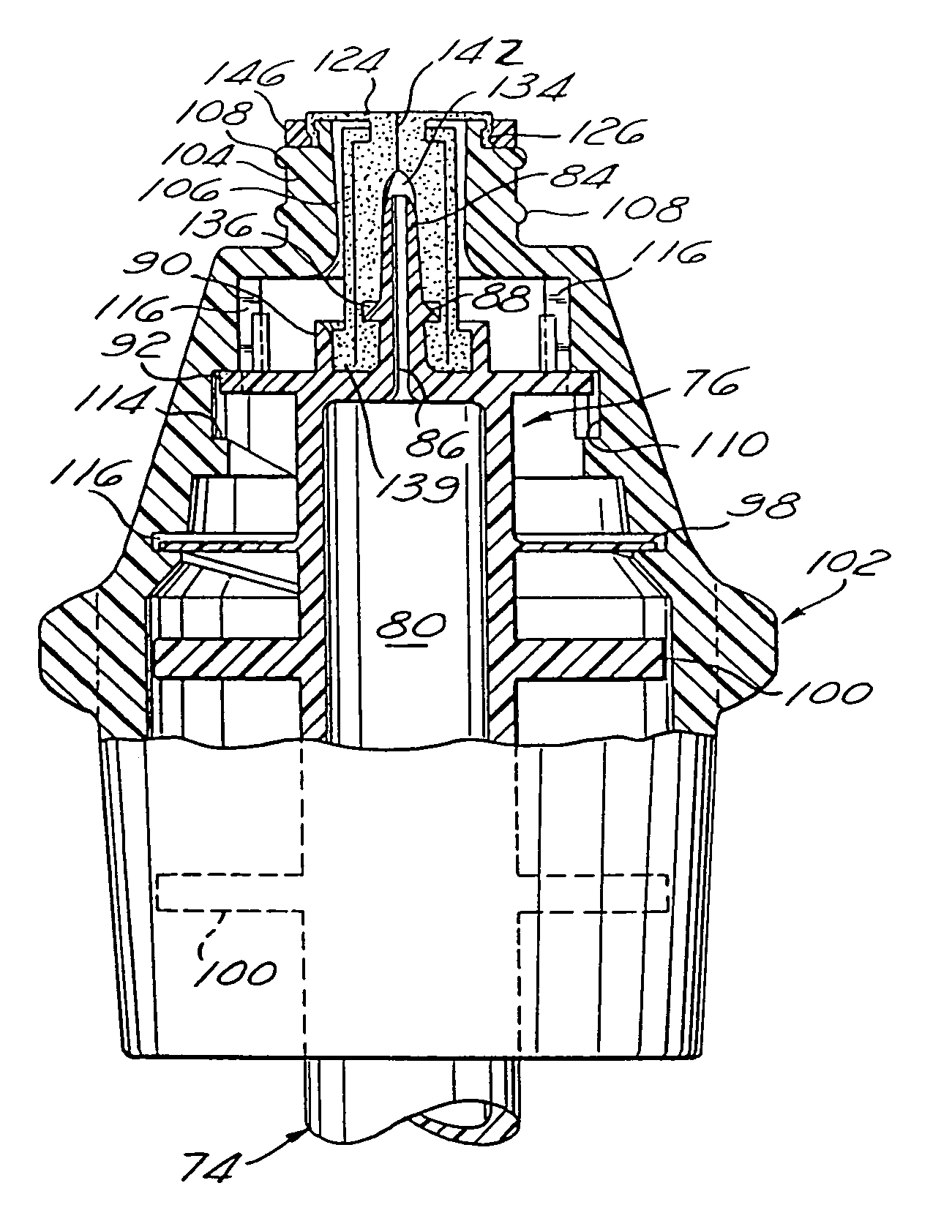
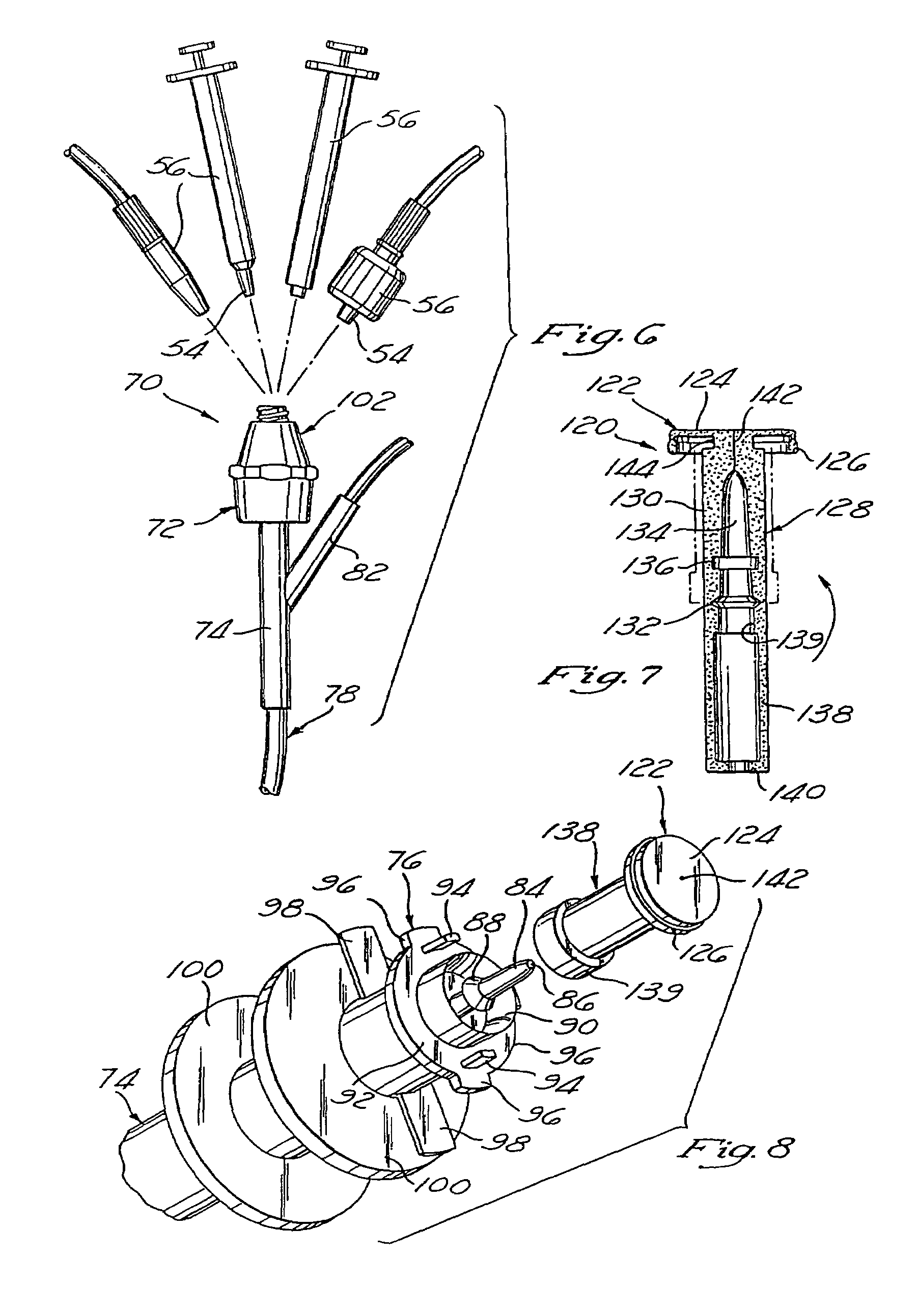
[0053]In the second embodiment, the housing 72 further comprises a hollow connector cap 102 which is attached to the proximal portion of the main body portion 74. The connector cap 102 includes an annular attachment region 104 formed on the proximal end thereof. The attachment region 104 defines a central opening 106 which communicates with the hollow interior of the connector cap 102. Additionally, formed on the outer surface of the attachment region 104 are Luer threads 108. The attachment of the connector cap 102 to the main body portion 74 is facilitated by the receipt of the stop tabs 96 into an annular channel 110 which is disposed within the inner surface of the connector cap 102 and defines a proximal stop surface 112 and a distal stop surface 114. When the stop tabs 96 are properly received into the channel 110, the extensions 94 formed on the proximal surface thereof are received into complimentary slots 116 which are disposed within the inner surface of the connector cap ...

third embodiment

[0065]Referring now to FIGS. 11–17, illustrated is a needleless injection site 160 constructed in accordance with the present invention. As will be described in more detail below, the injection site 160 is adapted to be selectively coupled to a Luer connector 162 (as shown in FIGS. 11 and 15), a standard tubular fluid line 164 (as shown in FIGS. 11 and 17), a Y-injection site (as shown in FIG. 16), and a bottle 168 (as shown in FIG. 12). However, it will be recognized that the injection site 160 may additionally be fluidly coupled to various other intravenous infusion components. The injection site 160 comprises a housing 170 which itself comprises an adapter member 172 defining a proximal end 174, a distal end 176 and an interior chamber 178.

[0066]Referring now to FIGS. 14–17, the adapter member 172 comprises an upper section 180 which defines the proximal end 174, and a lower section 182 which is rigidly attached to the upper section 180 and defines the distal end 176. The upper a...


PUM


Abstract

A needleless injection site comprising a housing defining proximal and distal ends and including a reseal member disposed therein. The reseal member has an elastically openable and closable aperture formed therein, and normally resides within the housing in a closed position wherein the aperture is in a closed configuration. The reseal member is deformable such that the application of distally directed pressure thereto will cause the reseal member to distally advance within the housing to an open position wherein the aperture assumes an open configuration. The removal of the distally directed pressure from the reseal member will cause it to resiliently return to the closed position wherein the aperture assumes the closed configuration.

Description

[0001]This application is a continuation of application Ser. No. 10 / 336,412 filed Jan. 3, 2003, which is a continuation of application Ser. No. 09 / 849,091 filed May 4, 2001 now U.S. Pat. No. 6,572,591 which is a continuation of application Ser. No. 09 / 226,664 filed Jan. 8, 1999, now U.S. Pat. No. 6,261,268, which is a continuation of application Ser. No. 08 / 550,748 filed Oct. 31, 1995, now U.S. Pat. No. 5,788,675, which is a divisional of application Ser. No. 08 / 262,994 filed Jun. 20, 1994, now U.S. Pat. No. 5,470,319.FIELD OF THE INVENTION[0002]The present invention relates generally to the medical arts, and more particularly to a needleless injection site for use in relation to intravenous infusions.BACKGROUND OF THE INVENTION[0003]It is common medical practice to intravenously infuse various fluids into the blood vessels of a patient. Such infusion is typically accomplished by the insertion of a hollow introducer needle into a target blood vessel. The introducer needle is fluidly...

Claims


Application Information

Patent Timeline
Patent Type & Authority Patents(United States)
IPC IPC(8): A61M5/00A61M5/178A61M25/16A61M39/04A61M39/26
CPCA61M39/045A61M39/26Y10S604/905A61M2039/267
Inventor MAYER, BRUNO FRANZ P.
Owner BECTON DICKINSON & CO
Why Eureka
Try Eureka