
Method and apparatus for predicting the life of a rolling bearing, rolling bearing selection apparatus using the life prediction apparatus, and storage medium

a life prediction and rolling bearing technology, applied in the direction of electric/magnetic computing, analogue processes for specific applications, instruments, etc., can solve the problems of dispersion of the life of the basic dynamic rating, insufficient degree of determining the service condition coefficient a/sub>3/sub>, and difficulty in quantifying, so as to achieve accurate prediction and simplify input conditions

Active Publication Date: 2006-02-28
NSK LTD
View PDF25 Cites 33 Cited by
  • Summary
  • Abstract
  • Description
  • Claims
  • Application Information

AI Technical Summary

Benefits of technology

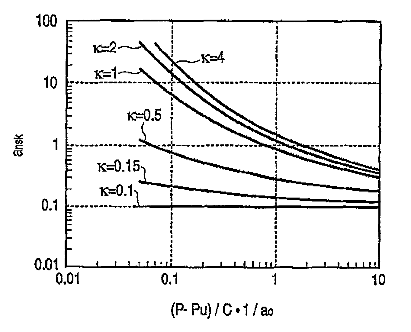
The invention provides a method and apparatus for predicting the life of a rolling bearing by accurately calculating the life correction coefficient aNSK based on the lubrication parameter aL and the load parameter {(P−Pu) / C}·1 / ac. The method takes into account the influence of steel and heat treatment on the life of the bearing, and the viscosity ratio κ of the lubricant. The apparatus includes data information inputting means for inputting data information including the basic dynamic load rating C and the basic static load rating C0 of the rolling bearing. The invention simplifies the prediction of the life of a rolling bearing and improves the accuracy of the prediction.

Problems solved by technology

In the corrected rating life Lna, however, it is difficult to quantify the bearing characteristic coefficient a2 and the service condition coefficient a3, and particularly the degree of determining the service condition coefficient a3 is insufficient.
Consequently, there arises a problem in that the basic dynamic rating life is dispersed.
As a result, there is an unsolved problem in which the life prediction cannot be correctly performed.
Therefore, it is very difficult to predict the life of an actual rolling bearing, and life prediction cannot be correctly performed.

Method used


Image

  • Method and apparatus for predicting the life of a rolling bearing, rolling bearing selection apparatus using the life prediction apparatus, and storage medium
  • Method and apparatus for predicting the life of a rolling bearing, rolling bearing selection apparatus using the life prediction apparatus, and storage medium
  • Method and apparatus for predicting the life of a rolling bearing, rolling bearing selection apparatus using the life prediction apparatus, and storage medium

Examples


example

[0191]In Table 3 below, shown are conditions and results of tests and experiments which were conducted with using a deep groove ball bearing of a designation number of “6206”, and calculation results of the conventional life calculation expression LCA which is calculated by (C / P)p while setting a1=a2=a3=1.0 and the new-life calculation expression LA of the invention. The tests were conducted at the revolution number N=5,000 rpm, and the test temperature was 40 to 145° C.

[0192]

TABLE 3{(P −Experi-ConventionalNewPu) / C} · 1 / mentexpressionexpressionP / CκacacL10 hrLCA hrLA hr10.10.11.00.1  5805,55656020.10.80.80.144,40043,340  30.11.50.50.291,04090,010  40.30.31.00.3   45  206 4150.310.50.6  39037160.320.30.9  35533070.50.51.00.5   28  44 2280.51.50.41.2   49 4890.530.22.4   43 40100.711.00.8   26  16 24110.721.00.8   37 35120.740.51.3   23 22

[0193]In Table 4 below, shown are conditions and results of tests and experiments which were conducted with using a tapered roller bearing of a desig...


PUM


Abstract

A dynamic equivalent load P is calculated from data information of a rolling bearing. Next, a reliability coefficient a1 is determined, a lubrication parameter aL corresponding to a used lubricant is calculated, and a contamination degree coefficient ac is determined in consideration of a material coefficient. A fatigue limit load Pu is calculated on the basis of the data information. Thereafter, a load parameter {(P−Pu) / C}·1 / ac is calculated. On the basis of the lubrication parameter aL and the load parameter {(P−Pu) / C}·1 / ac, a life correction coefficient aNSK is calculated with reference to a life correction coefficient calculation map. The bearing life LA is calculated by LA=a1·aNSK·(C / P)p.

Description

BACKGROUND OF THE INVENTION[0001]1. Field of the Invention[0002]The present invention relates to a method and an apparatus which can correctly predict the life of a rolling bearing having a specification that enables the basic dynamic load rating and the basic static load rating to being calculable, a rolling bearing selection apparatus using the life prediction apparatus, and a storage medium storing a program for life prediction.[0003]2. Description of the Related Art[0004]The basic rating life L10 of a rolling bearing is defined in JIS B1518: 1992, and usually calculated by the following expression:L10=(C / P)p  (1)where C is a basic dynamic load rating of the rolling bearing, P is a dynamic equivalent load which acts on the bearing, and p indicates a load index that is set to p=3 in the case of a ball bearing, and to p=10 / 3 in the case of a roller bearing. The basic rating life L10 indicates the life in the case where the reliability is 90%, usual materials are used, and the beari...

Claims


Application Information

Patent Timeline
Patent Type & Authority Patents(United States)
IPC IPC(8): G06F17/10G06F7/60F16C19/00F16C19/52G01M13/04G07C3/00
CPCF16C19/00G07C3/00G01M13/04
Inventor TAKEMURA, HIROMICHIMURAKAMI, YASUO
Owner NSK LTD
Learn More