
Laser system with fiber-bound communication

a fiber-bound communication and laser system technology, applied in the field of laser systems, to achieve the effect of easy integration and reliable data exchang

Active Publication Date: 2006-02-28
DORNIER MEDTECH LASER GMBH
View PDF17 Cites 68 Cited by
  • Summary
  • Abstract
  • Description
  • Claims
  • Application Information

AI Technical Summary

Benefits of technology

[0012]The present invention, according to exemplary embodiments described herein, provides a laser system that permits a reliable exchange of data between the hand-piece and the stationary unit. The invention takes into account the ergonomic demands that have to be fulfilled by the hand-piece, which is adapted to be easily integrated in existing laser systems without resulting in additional difficulties as far as the world-wide admission of the laser unit. The present invention is based on the finding that data can be transmitted from the hand-piece to the stationary unit of the laser by utilizing the light-guide which is used for the therapy laser.
[0013]The present invention can enable data communication between the hand-piece and the stationary unit of the laser system in the case of which additional cables are not necessary between the hand-piece and the laser, and admission procedures for a worldwide admission of the system are not influenced negatively due to RF components. Furthermore, problems with the reliability of data communication, which may arise, for example, in the case of directed or diffuse infrared transmission, can be avoided. The solution according to exemplary embodiments of the present invention additionally offers the advantage that it is adapted to be integrated in existing systems, primarily in view of the fact that it hardly interferes with the complicated optics of the laser system. In certain laser systems, existing system components can also be used for the solution according to the present invention, whereby the outlay for an integration of data transmission from the hand-piece to the stationary unit can be reduced still further.

Problems solved by technology

Each of these three transmission possibilities has certain specific drawbacks with respect to handiness, power consumption and effectiveness of the method, or they lead to problems as far as a worldwide approval of the laser system is concerned.

Method used


Image

  • Laser system with fiber-bound communication
  • Laser system with fiber-bound communication
  • Laser system with fiber-bound communication

Examples


Embodiment Construction

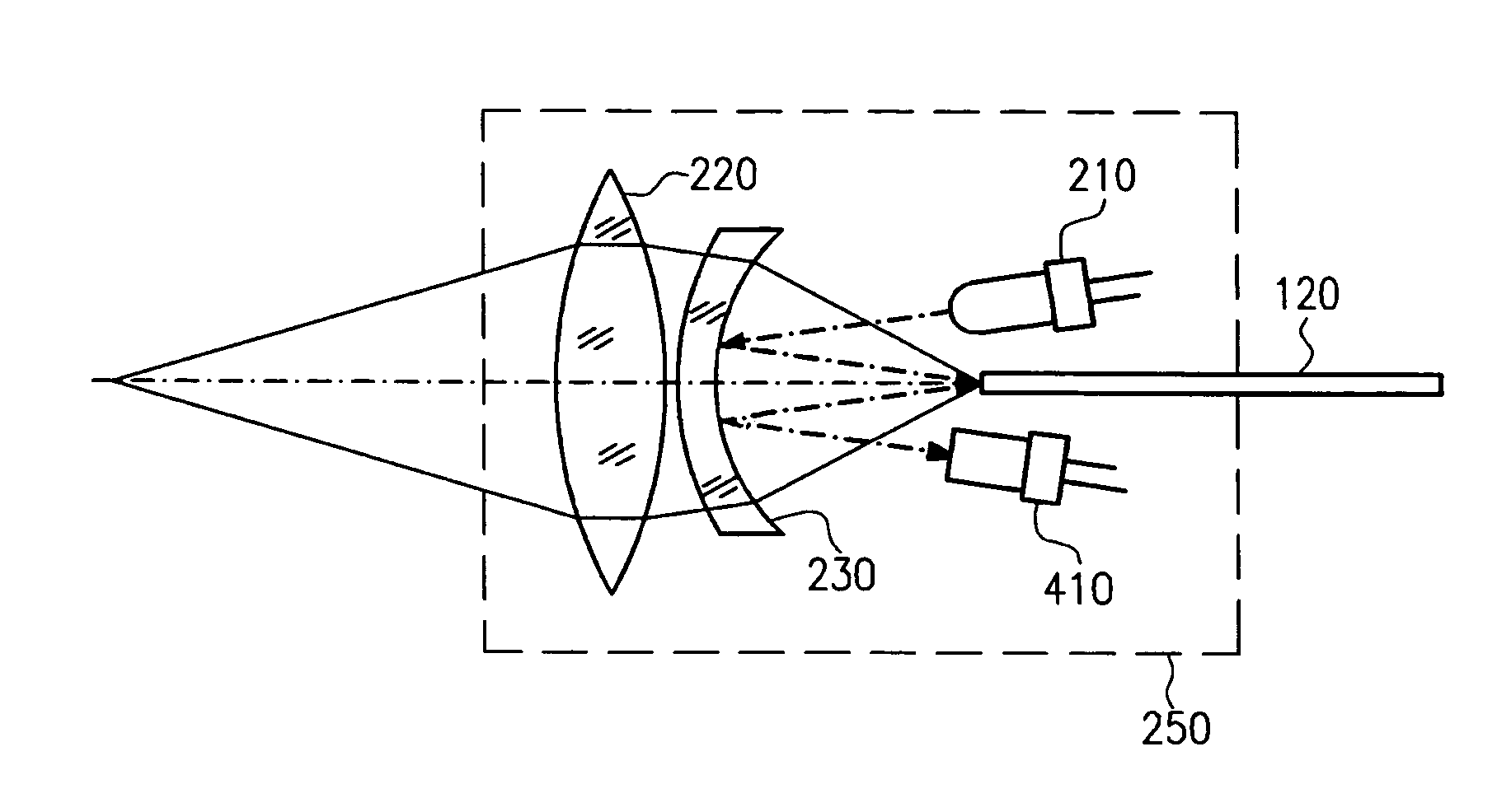
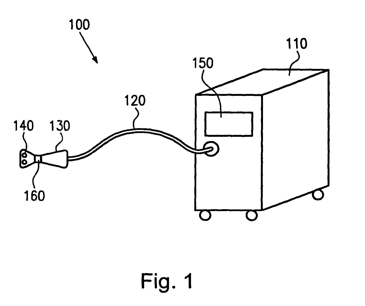
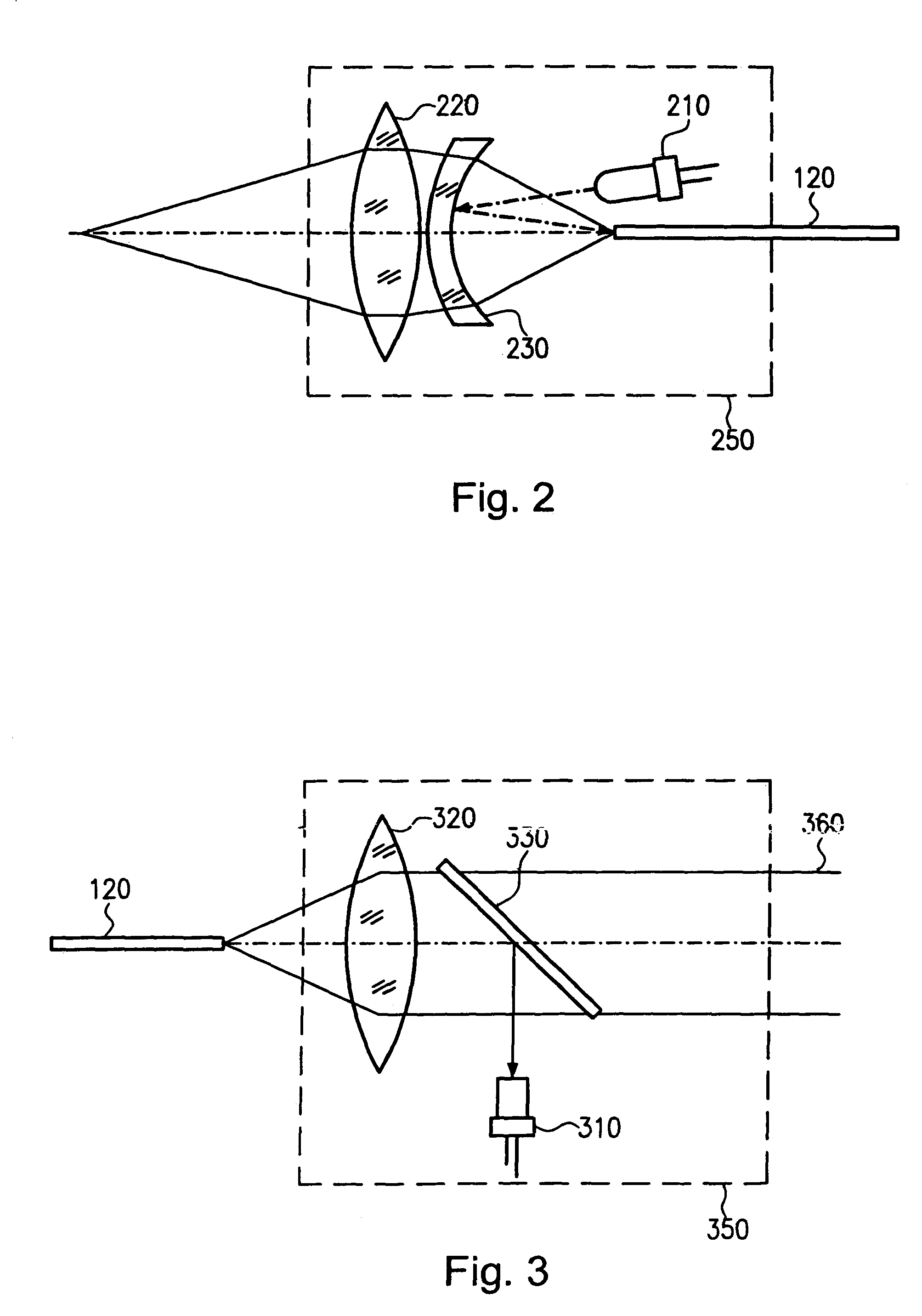
[0028]The illustrative embodiments of the present invention will be described with reference to the drawings, wherein like elements and structures are indicated with like reference numbers. FIG. 1 shows, on the basis of a schematic diagram, an exemplary embodiment of the present invention. The laser system 100 comprises a stationary or transportable laser unit 110 including a means for generating laser radiation, which has coupled thereto a flexible light-guide 120 connected to a hand piece 130. For producing intensive laser radiation, the laser unit 110 can be equipped with high-power laser diodes, a microoptical system for focusing the laser light produced, and a power supply. Alternatively, the laser unit can be equipped with a laser medium, a resonator, and a pumping source, as well as with a suitable power supply. In this case, diode-pumped solid-state laser media are typically used for generating the intensive laser radiation.

[0029]In addition, the laser unit 110 can include a...


PUM

PropertyMeasurementUnit
Electric energyaaaaaaaaaa
Poweraaaaaaaaaa
Transparencyaaaaaaaaaa

Abstract

A laser system is provided that includes a laser unit, an incoupling means for coupling the laser radiation into a light-guide, and an outcoupling means for coupling the laser radiation out from the light-guide. A data transmitting means is coupled to the incoupling means or outcoupling means and produces optical signals which are coupled into the light-guide via the incoupling means or the outcoupling means. These optical signals are received by a data receiving means at the other end of the light-guide. The laser system can be used for realizing a data communication between the hand-piece and the stationary unit of the laser system in the case of which additional cables between the hand-piece and the laser are not necessary for transmitting data.

Description

CROSS REFERENCE TO RELATED APPLICATION[0001]This application claims priority to co-pending German Patent Application No. 102 36 175.4, which was filed on Aug. 7, 2002 and is incorporated herein by reference.FIELD OF THE INVENTION[0002]The present invention generally relates to a laser system for medical applications, and more particularly, to a laser system with fiber-bound communication.BACKGROUND OF THE INVENTION[0003]Laser light has gained acceptance as a controllable light source not only in scientific research but also in many fields of everyday life. This is primarily due to the fact that a laser provides a monochromatic light source with coherent radiation which can be focused very well due to the small divergence. The use of lasers has become increasingly common not only in the field of telecommunications and entertainment electronics but also for treating materials and for medical purposes. In the latter field, it has been of decisive importance that a laser is an instrumen...

Claims


Application Information

Patent Timeline
IPC IPC(8): G02B6/42A61B18/18G02B6/32A61B18/22B23K26/00H04B10/50
CPCA61B18/22H04B10/503B23K26/0096A61B2017/00477
Inventor ILLICH, WOLFGANGAUSTEN, JURGENHIERETH, WERNER
Owner DORNIER MEDTECH LASER GMBH
Learn More