Illumination system and method for efficiently illuminating a pattern generator

Inactive Publication Date: 2006-02-28
ASML HLDG NV
View PDF37 Cites 15 Cited by
  • Summary
  • Abstract
  • Description
  • Claims
  • Application Information

AI Technical Summary

Benefits of technology

[0018]An embodiment of the present invention provides a system that substantially increases optical efficiency and substantially reduces or eliminates the generation of stray light generated when illumination light impinges on undesired areas of a pattern generator. The system includes a light source, a pupil defining element (PDE), a field defining element (FDE), an optical system, and the pattern generator. The PDE and FDE can be diffractive or refractive devices. Light emitted from the light source is transmitted through the PDE and FDE to form shaped and directed beams that are directed onto one or more desired illumination areas of the pattern generator and are directed substantially away from undesired areas of the pattern generator.
[0019]Other embodiments of the present invention include a method that substantially increases optical efficiency and substantially reduces or eliminates the generation of stray light generated when illumination light interacts with a pattern generator (e.g., a reflective or transmissive reticle or SLM). The method includes transmitting light through a PDE and a FDE to form beams of light, directing the beams of light using an optical system towards the pattern generator, and substantially illuminating only the desired illumination areas of the pattern generator and substantially no undesired areas of the pattern generator, based on the transmitting and directing steps.

Problems solved by technology

Thus, a substantial amount of the light directed to the pattern generator may not impinge on the desired illumination area of the pattern or the active area, but instead impinges on undesired areas of the pattern or the inactive areas, which can result in stray light and / or wasted light.
The stray light reaching the surface of the substrate can cause errors in devices being fabricated on the substrate.

Method used


Image

  • Illumination system and method for efficiently illuminating a pattern generator
  • Illumination system and method for efficiently illuminating a pattern generator
  • Illumination system and method for efficiently illuminating a pattern generator

Examples


Embodiment Construction

Overview

[0029]While specific configurations and arrangements are discussed, it should be understood that this is done for illustrative purposes only. A person skilled in the pertinent art will recognize that other configurations and arrangements can be used without departing from the spirit and scope of the present invention. It will be apparent to a person skilled in the pertinent art that this invention can also be employed in a variety of other applications.

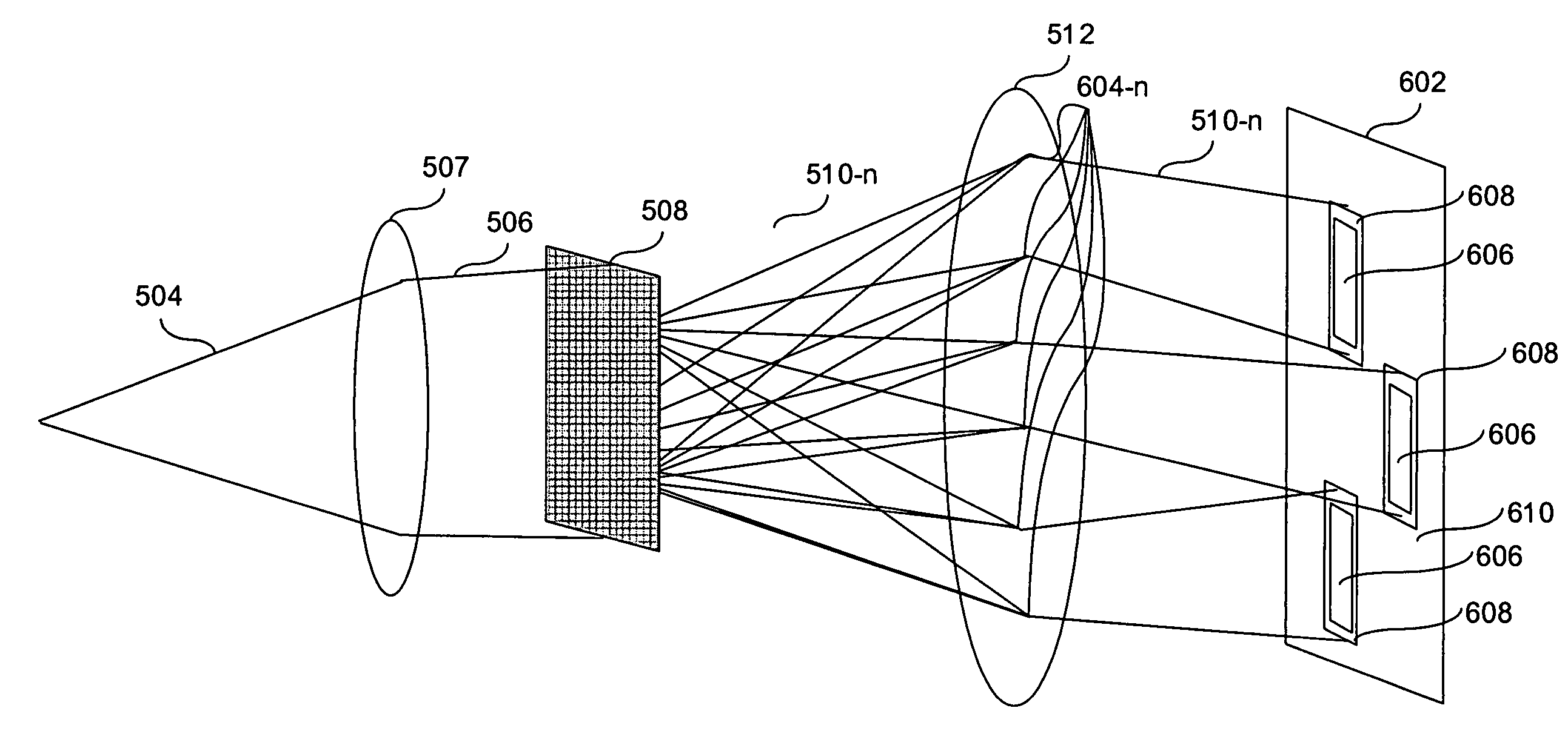
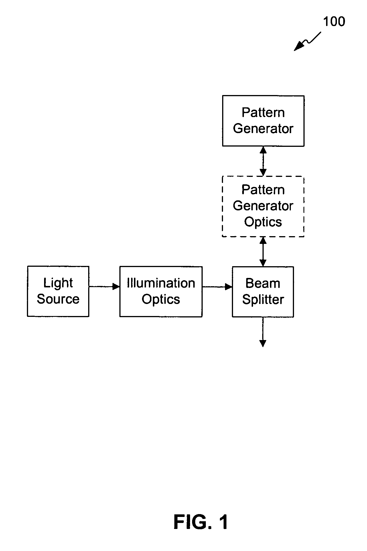
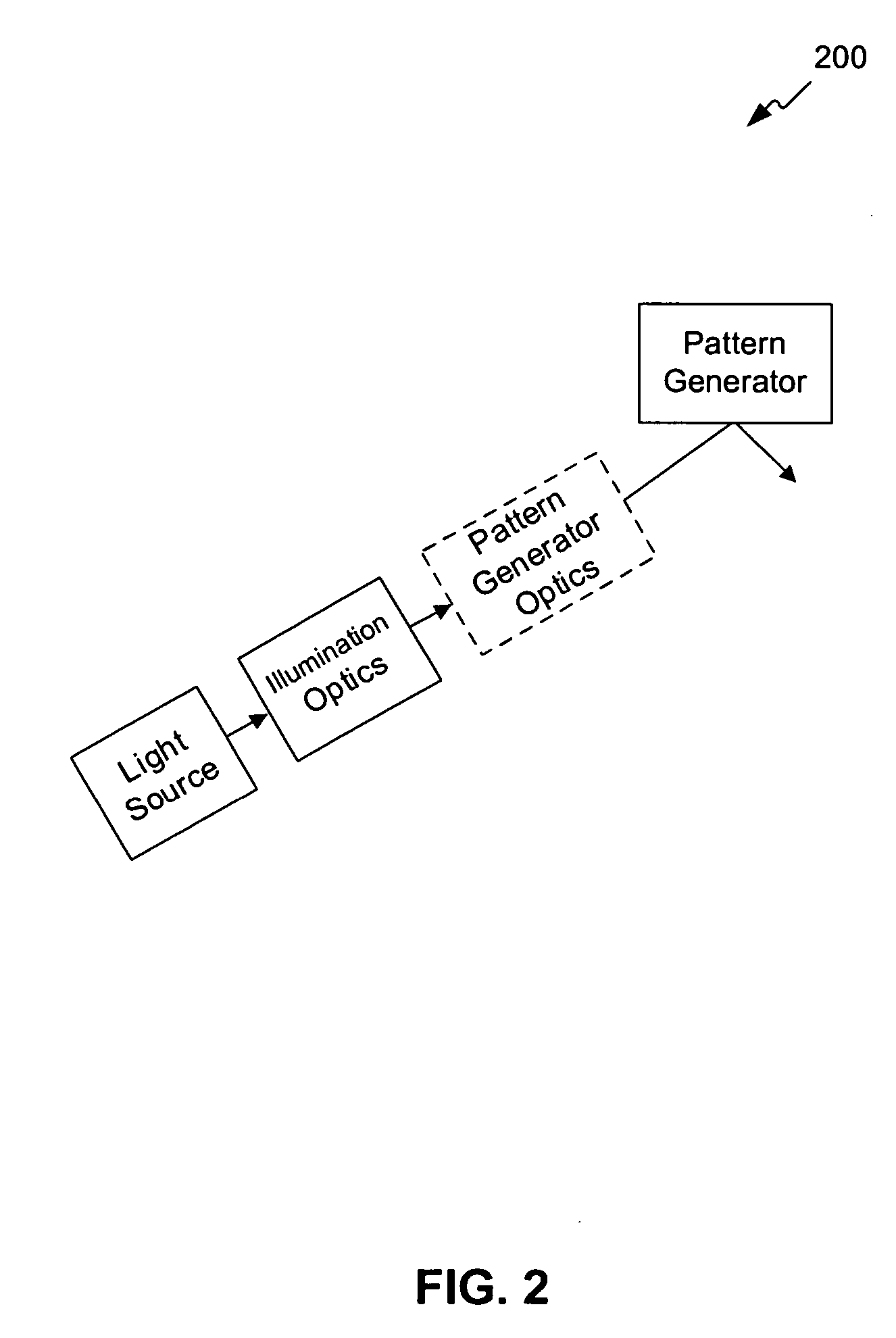
[0030]An embodiment of the present invention provides an illumination system having a light source and illumination optics. The illumination system is used to illuminate a pattern generator. The illumination optics include at least two devices. For example, if first and second diffractive and / or refractive devices are used, one can be a pupil defining element (PDE) and one can be a field defining element (FDE). In another example, a third diffractive or refractive element can be used to make light entering the illumination sys...


PUM


Abstract

An illumination method and system use a light source and illumination optics to illuminate a pattern generator. The illumination optics can include at least two devices. For example, if first and second diffractive and / or refractive devices are used, one can be a pupil defining element (PDE) and one can be a field defining element (FDE). In another example, a third diffractive or refractive element can be used to make light entering the illumination system uniform. When only two are used, the PDE forms one or more light beams having a defined profile. The FDE directs the one or more light beams having the defined profile, such that each directed beam substantially corresponds in size and shape to a desired illumination area(s) on the pattern generator. The directed beams are directed to impinge substantially only on the desired illumination area(s). Thus, using the PDE and the FDE increases optical efficiency of light impinging on the pattern generator and substantially reduces or eliminates stray light caused by light impinging on undesired areas of the pattern generator.

Description

CROSS REFERENCE TO RELATED APPLICATIONS[0001]This application is a continuation-in-part of U.S. Ser. No. 10 / 270,556, filed Oct. 16, 2002 now U.S. Pat. No. 6,775,069 entitled “Advanced Illumination System for Use in Microlithogrpahy,” (published as U.S. Patent Application Publication No. 2003 / 0076679 A1 on Apr. 24, 2003), which claims benefit under 35 U.S.C. 119(e) to U.S. Provisional Application No. 60 / 329,758, filed Oct. 18, 2001, which are both incorporated herein by reference in their entireties.[0002]This application is also a continuation-in-part of U.S. Ser. No. 10 / 166,062, to Oskotsky et al., entitled “Advanced Illumination System for Use in Microlithography,” filed Jun. 11, 2002 (now U.S. Patent Application Publication No. 2003 / 0227609 A1), which is incorporated by reference herein in its entirety.[0003]This application is related to U.S. Ser. No. 10 / 812,978, filed Mar. 31, 2004 (1857.0700003), which is incorporated by reference herein in its entirety.BACKGROUND OF THE INVEN...

Claims


Application Information

Patent Timeline
IPC IPC(8): G02B27/10G03F7/20
CPCG02B27/0905G03F7/70083G03F7/70291G03F7/70183G03F7/70158B41J2/451
Inventor COSTON, SCOTTCEBUHAR, WENCESLAO A.HINTERSTEINER, JASON D.
Owner ASML HLDG NV
Why Eureka
Try Eureka