
Method and objective lens for spectrally modifying light for an electronic camera

a technology of electronic cameras and objective lenses, applied in camera filters, instruments, television systems, etc., can solve the problems of spectral response using these types of filters, color from a video segment to a film segment will change, and the color of a video segment may be objectionable or at least noticeable,

Inactive Publication Date: 2006-02-28
COURTLAND CAPITAL MARKET SERVICES LLC +1
View PDF21 Cites 18 Cited by
  • Summary
  • Abstract
  • Description
  • Claims
  • Application Information

AI Technical Summary

Benefits of technology

[0005]Traditionally, colored filters on dyed glass, gelatin, or plastic substrates have been used to modify by absorption the spectral characteristics of light in photographic processes. However, the slope (i.e. the tangent of the angle on a graph of light wavelengths) of the spectral response using these types of filters, which work by the selective absorption of light of different wavelengths, is very gradual and hard to control. Interference filters, which consist of a series of very thin coatings which result in constructive and destructive interference of particular wavelengths can have much steeper slopes, higher efficiency, and more complex but predictable bandpass characteristics, than absorption type filters. The major disadvantage of an interference type of filter for photographic applications is that their spectral characteristics can vary greatly depending on the incident angle of the light ray at the surface of the filter coating. This could mean for instance that such a filter, used with a zoom lens, would vary in its spectral characteristics as the focal length and hence the angle of view of the lens was changed.
[0007]It is an object of the present invention to provide a method and objective lens for use with an electronic camera for modifying the light passing through the lens to a predetermined spectrum of light rays being supplied to the electronic camera for causing the camera to record a desired colorimetry, shading or the like.
[0008]In the preferred embodiment of the present invention, the objective lens is provided with an optical element on the optical axis at a location where the light rays are substantially collimated and a coating is provided on that optical element to perform as an interference filter for producing the predetermined spectrum of light for the electronic camera. Preferably, that optical element is of zero optical power for minimizing the optical effect thereof and is replaceable with comparable optical elements having either different coatings for producing different predetermined spectrums of light rays or no coating for allowing the natural spectrum of light waves to be supplied to the electronic camera. A further object of this invention is to provide a lens with such an optical element with interference filter coatings that produce a predetermined spectrum of light waves supplied to the video camera that can match a specific spectrum recorded on film, match real colors, produce desired shading or the like.

Problems solved by technology

However, film colorimetry has mostly departed from “ideal” colorimetry for both aesthetic and technical reasons.
Thus, if both video and film cameras are used for different segments of a single production, the color from a video segment to a film segment will change and may be visually objectionable or at least noticeable.
However, the slope (i.e. the tangent of the angle on a graph of light wavelengths) of the spectral response using these types of filters, which work by the selective absorption of light of different wavelengths, is very gradual and hard to control.
The major disadvantage of an interference type of filter for photographic applications is that their spectral characteristics can vary greatly depending on the incident angle of the light ray at the surface of the filter coating.
It should be noted that introducing such an interference filter in front of the lens is possible but due to the varying angles of light beams over the field of view the spectral characteristics of the filter will vary which is a disadvantage.
Also, depending on the focal length and aperture of the lens, the filter may become very large in size, weight and cost.
Further, by locating an interference type filter in the video camera after the lens, the filter will encounter light beams which are convergent and hence the same problem arises concerning the resultant spectral characteristics.

Method used


Image

  • Method and objective lens for spectrally modifying light for an electronic camera
  • Method and objective lens for spectrally modifying light for an electronic camera
  • Method and objective lens for spectrally modifying light for an electronic camera

Examples


Embodiment Construction

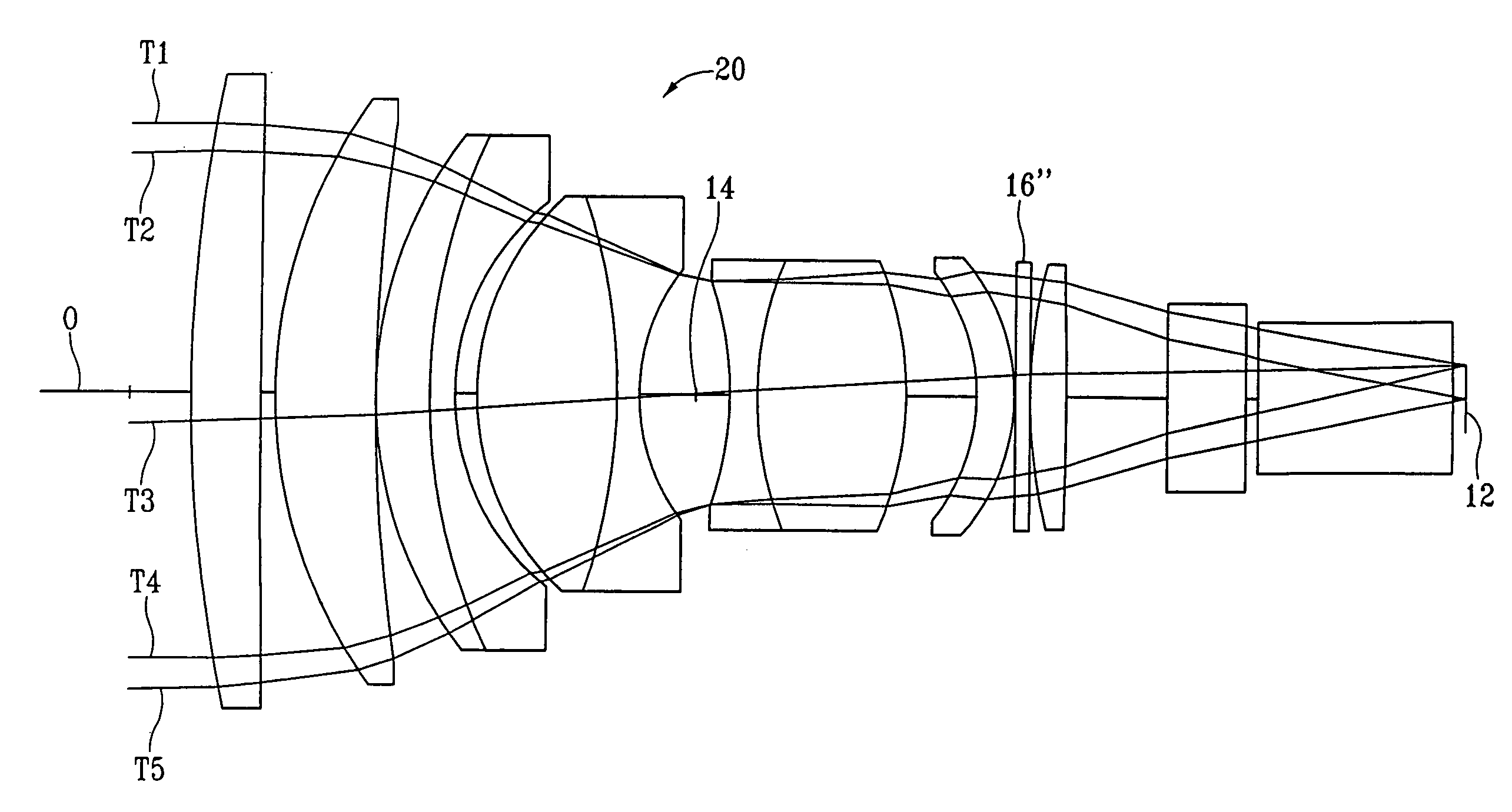
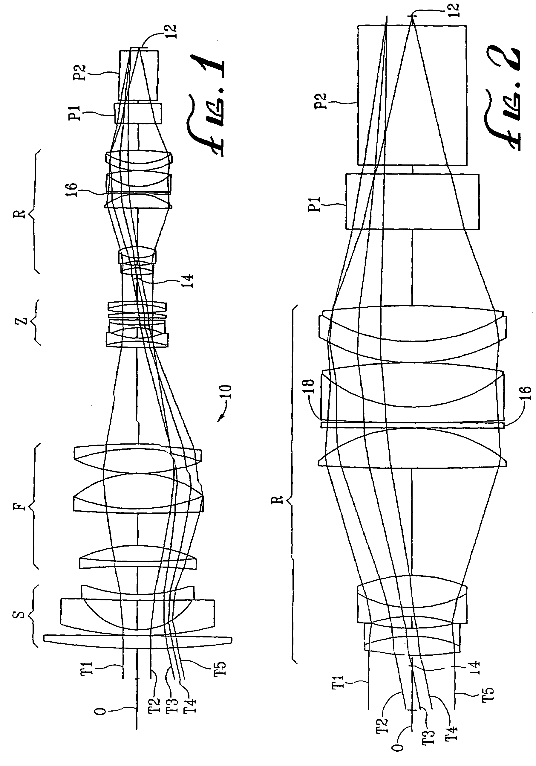
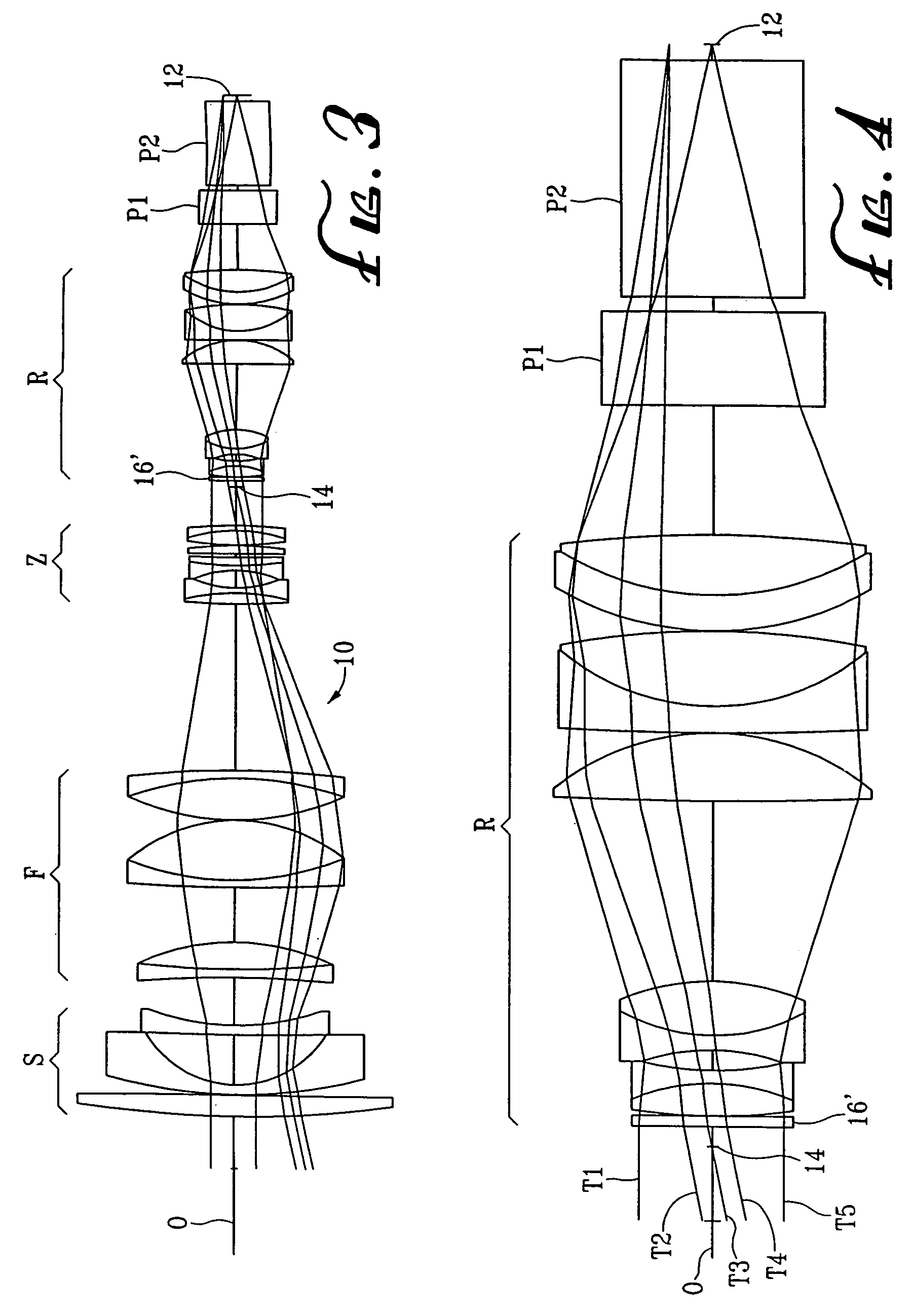
[0019]The present invention will be described in connection with two different types of high performance lenses, namely, a high performance zoom lens shown in FIGS. 1–4 and a high performance prime or fixed focal length lens shown in FIG. 5, which lenses are of a quality for use in cinematography, high definition television, advanced television and the like. The zoom lens of FIGS. 1–4 and the prime lens of FIG. 5 are lenses that include the interference filter element and method of the present invention in an appropriate manner but are otherwise conventional lenses, although it may be beneficial in some instances to specifically design a lens with appropriate characteristics for using the present invention.

[0020]Referring now to FIG. 1, the zoom lens 10 has the requisite groups of lens elements including a stationary objective lens group S, a focus lens group F, a zoom lens group Z, and a relay lens group R, with prisms P1 and P2, aligned on an optical axis O from the front of the l...


PUM


Abstract

A method for modifying the spectrum of light rays passing through an objective lens to an electronic camera that includes providing an interference type filter within the objective lens. The interference type filter may be a coating on a separate optical element added to the objective lens or on a normal optical component of the objective lens. The interference filter coating is located along the optical axis where the light rays are substantially collimated and have a minimum light ray incidence angle with respect to the coating surface, which angle should not exceed 15 degrees for any of the light rays passing therethrough.

Description

CROSS-REFERENCE TO RELATED APPLICATION[0001]This application is related to application Ser. No. 09 / 663,277, filed on Sep. 15, 2000, which application is specifically incorporated herein, in its entirety, by reference.[0002]The present invention relates to an objective lens for an electronic camera and, in particular, to such a lens and method for spectrally modifying the light supplied to the camera to a predetermined spectrum of light rays for any desired purpose.[0003]Recent advances in Charge Coupled Device (CCD) technology have enabled electronic cameras to be built having resolution capabilities which rival conventional 35 mm motion picture film. Video cameras are being developed using high resolution CDDs (approximately 2 million pixels per color) which will operate at the nominal frame speed of a motion picture camera (24 frames per second). These cameras are being developed as replacements for film cameras, at least for some applications. However, for the foreseeable future ...

Claims


Application Information

Patent Timeline
IPC IPC(8): H04N5/225G03B17/00H04N5/72G02B5/28G03B11/00G03B19/06
CPCG02B5/285
Inventor NEIL, IAIN A.GALT, JOHN J.
Owner COURTLAND CAPITAL MARKET SERVICES LLC
Learn More