
Soil water potential detector

a technology of soil water and detector, applied in the field of soil water detector, can solve the problems of limited soil water retention, limited proper tools used for irrigation, and limitations of existing devices

Active Publication Date: 2006-02-28
HORTAU
View PDF17 Cites 9 Cited by
  • Summary
  • Abstract
  • Description
  • Claims
  • Application Information

AI Technical Summary

Benefits of technology

"The present invention provides a porous probe made of agglomerated material that can be inserted into a solid medium, such as soil, to detect the presence or absence of a liquid, such as water. The optical properties of the probe are modified depending on the level of liquid saturation. The invention also includes a device for measuring the availability of a liquid in a solid, which comprises a probe and means for detecting light translucency in the probe. The technical effects of the invention include improved accuracy and efficiency in detecting the presence of liquid in a solid and the ability to measure liquid levels in real-time."

Problems solved by technology

However, as a result of this fast drainage, soil water retention is limited.
In addition to the fact that the risk of drought increases with global warming, the proper tools used to initiate irrigation are limited.
However, the existing devices suffer from limitations.
These technologies however face important reliability problems since the length of the electrodes needed with such technology in small size pot is not sufficient and their price is very high.
Moreover, these systems require calibration to infer water potential and therefore lack of accuracy, especially in organic growing media.
Other types of sensors which directly measure soil water potential are accurate but are very expensive and tricky to use.
Indeed, the output signal of these sensors often need a human interpretation and most of these devices have to be routinely calibrated.
Finally, most of the proposed sampling devices are not designed to properly start the irrigation and without signal interpretation neglect the adequate interruption of irrigation.
Although this technology appeared promising, nylon filter coupled with LED gave unreliable results.
Unfortunately, these important characteristic cannot be reached with the nylon filter.
Moreover, it is known in the art that nylon filters provide an output signal that needs interpretation, a feature convenient for researchers but inappropriate for growers.

Method used


Image

  • Soil water potential detector
  • Soil water potential detector

Examples


Embodiment Construction

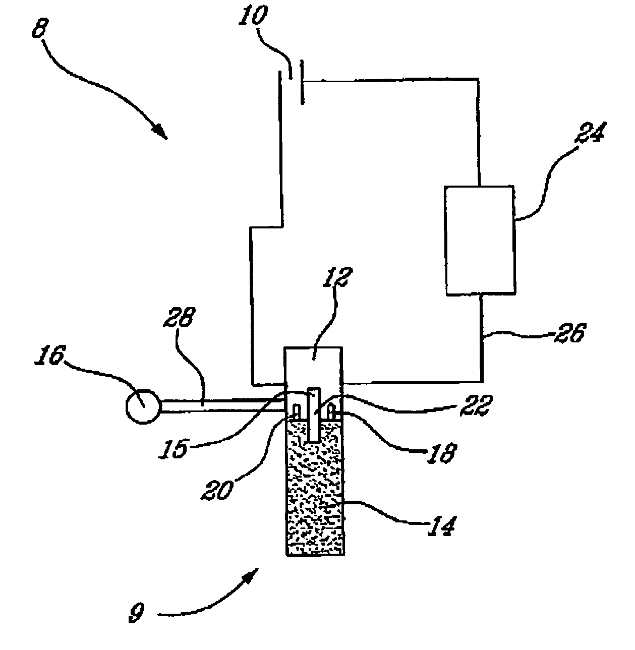
[0025]With reference to the drawing, it will be seen that a liquid detector 8 according to the invention comprises a probe generally identified by reference numeral 9, that consists of a cylindrical porous member 14 made of a light impervious, porous, fritted material that will be described more in detail later. It will be understood that the porous member 14 is fixed to a cylindrical support 12 as shown.

[0026]Also as shown, liquid detector 8 includes a circuitry permitting to determine if water is available for the purpose of the grower.

[0027]More particularly, it will be seen that porous member 14 has an upper portion 15 that extends inside support 12 as shown. Inside support 12, there is also provided an LED diode 18 that emits light rays in a direction transverse to upper portion 15. In addition, there is provided a photodiode 20 that is also mounted inside support 12 in known manner and that operates in response to light 22 emitted by the LED diode 18. If the light emitted by L...


PUM

PropertyMeasurementUnit
diameteraaaaaaaaaa
translucentaaaaaaaaaa
light translucencyaaaaaaaaaa

Abstract

The present invention related to a water detector for use in determining the presence of sufficient water in irrigation systems and plant cultures in general. The detector includes a probe and the presence of water in a soil induces modifications in the optical properties of the probe. The optical properties are monitored and used to control the activation or deactivation of the irrigation system, emit a warning signal or provide a reference value of water potential for monitoring purposes.

Description

BACKGROUND OF THE INVENTION[0001]i) Field of the Invention[0002]The present invention relates to a soil water detector and more particularly to a device for monitoring water potential within a soil. The present invention also relates to a water potential detector for an irrigation system comprising a probe that allows the monitoring of water content within the soil.[0003]ii) Description of Prior Art[0004]Saving irrigation water is an increasing concern among growers. Actually, reliable soil water content or suction measurements are the basics of a proper irrigation management for saving water and fertilisers. In nursery and greenhouse production, the water available to plants is stored within the potted substrate. As the amount of water remains limited by the volume of the container, additional water therefore needs to be added to the crop through different irrigation systems. Irrigation water is also needed for vegetable and orchard crops to improve yield, since such productions ar...

Claims


Application Information

Patent Timeline
Patent Type & Authority Patents(United States)
IPC IPC(8): G01N15/06A01G25/16
CPCA01G25/167
Inventor CARON, JEANBOUDREAU, JOCELYN
Owner HORTAU
Learn More