Eureka AIR delivers breakthrough ideas for toughest innovation challenges, trusted by R&D personnel around the world.

Method and device for error concealment in an encoded audio-signal and method and device for decoding an encoded audio signal

a technology of error concealment and encoded audio, applied in the field of encoded audio signal decoding, can solve the problems of sudden rise in signal energy when the decoder issues error-free data again, adverse effects on the transmission of encoded audio signals, interrupting reproduction, etc., and achieve the effect of reducing computation effort and dependence on the transform algorithm used

Inactive Publication Date: 2006-02-21
FRAUNHOFER GESELLSCHAFT ZUR FOERDERUNG DER ANGEWANDTEN FORSCHUNG EV
View PDF10 Cites 100 Cited by
  • Summary
  • Abstract
  • Description
  • Claims
  • Application Information

AI Technical Summary

Benefits of technology

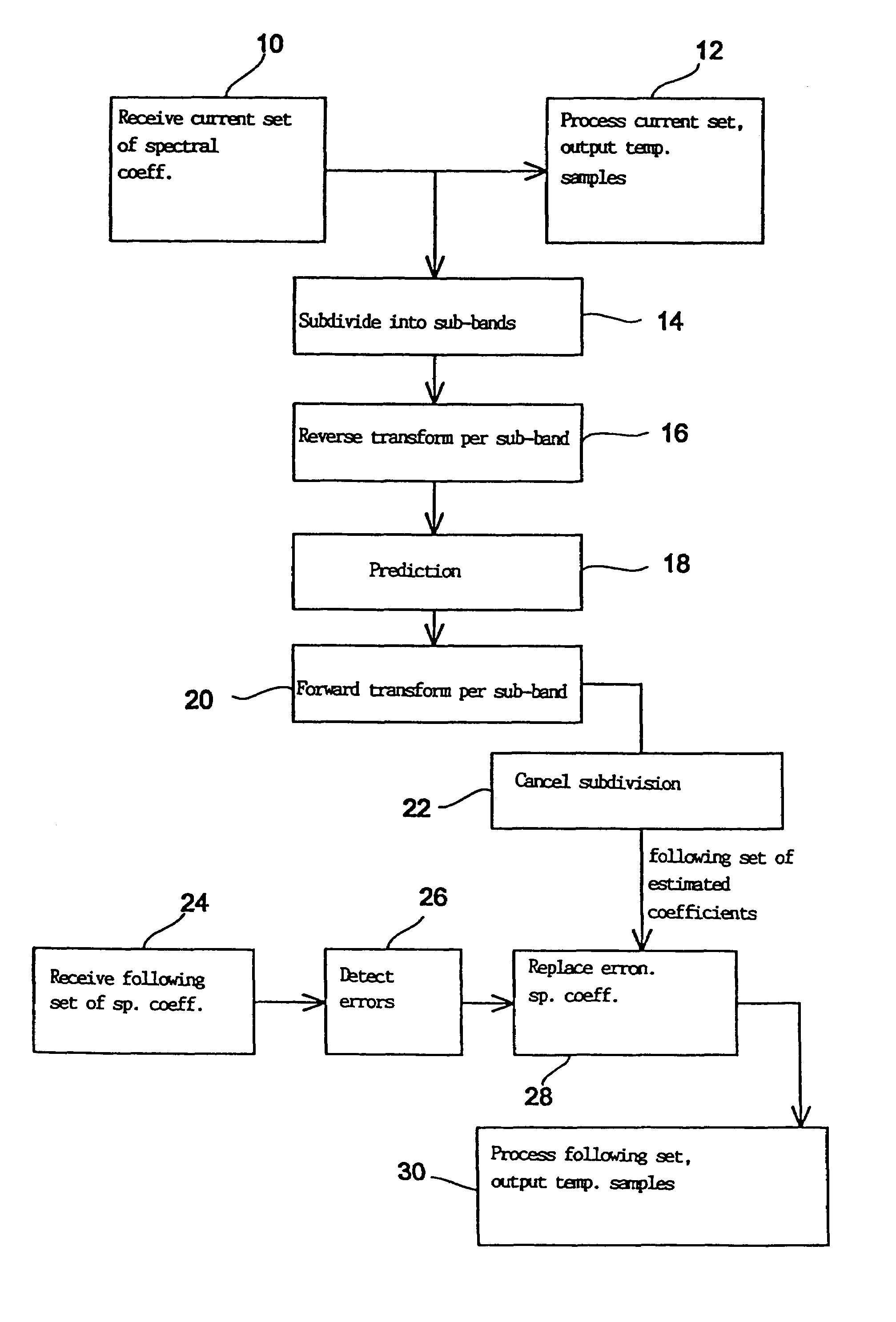
The present invention provides a method for accurately concealing errors in encoded audio signals. The method involves subdividing the spectral coefficients of the audio signal into sub-bands with different frequency ranges, reverse transforming them to obtain a temporal representation, performing a prediction using the temporal representation to obtain an estimated temporal representation, and using the estimated spectral coefficients to conceal any erroneous spectral coefficients in the following set. The invention also provides a device for decoding and concealing errors in encoded audio signals. The technical effect of the invention is to provide precise and flexible error concealment for audio signals with minimal computational effort and an error-tolerant decoding process.

Problems solved by technology

The transmission channel involved in the transmission of encoded audio signals by means of digital radio or over line-based networks is not ideal, which can result in encoded audio signals being adversely affected during the transmission.
When a decoder recognizes that data are missing or are erroneous, it interrupts the reproduction.
Because of psychoacoustic effects, however, the resulting sudden fall in the signal energy and its sudden rise when the decoder issues error-free data again is found disconcerting.
This method produces disturbing artefacts, however.
If longer parts are repeated, certain echo effects arise which are also found disturbing.
A disadvantage of this method is the relatively high computational effort, which makes a real-time decoding of a received multimedia or audio data signal impossible at present.
A further important disadvantage of this method results from the transform algorithm, namely the modified discrete cosine transform (MDCT)], which is used.
It is generally known that the MDCT algorithm does not provide an ideal Fourier spectrum but a “spectrum” which deviates from an ideal Fourier spectrum.
A spectral value prediction of MDCT spectral coefficients has thus shown itself to be inadequate when high precision is required.
A further disadvantage of spectral value prediction, particularly in connection with modern audio coding methods, is that modern audio coding methods use different window lengths or window shapes.
This means, however, that for a spectral value prediction both the window length and the window shape (in addition there are transition windows to initiate windowing from short to long blocks and vice versa)] must be constantly taken into account, which also increases the complexity of the spectral value prediction and would greatly affect the computational efficiency.

Method used


Image

  • Method and device for error concealment in an encoded audio-signal and method and device for decoding an encoded audio signal
  • Method and device for error concealment in an encoded audio-signal and method and device for decoding an encoded audio signal
  • Method and device for error concealment in an encoded audio-signal and method and device for decoding an encoded audio signal

Examples


Embodiment Construction

[0034]FIG. 1 shows a block diagram of a decoder according to a preferred embodiment of the present invention. The decoder block diagram shown in FIG. 1 corresponds essentially to the MPEG-2 AAC decoder as defined in the standard MPEG-2 AAC 13818-7. The encoded audio signal is first fed into a bit stream demultiplexer 100 in order to separate spectral data and side information. The Huffman coded spectral coefficients are then fed into a Huffman decoder 200 so as to obtain quantized spectral values from the Huffman code words. The quantized spectral values are then fed into an inverse quantizer 300 and the respective scale factor bands are then multiplied by appropriate scale factors. The decoder according to the present invention can incorporate a plurality of additional functional units following the inverse quantizer 300, e.g. a middle / side stage, a predictor stage, a TNS stage, etc., as specified in the standard.

[0035]According to a preferred embodiment of the present invention th...


PUM


Abstract

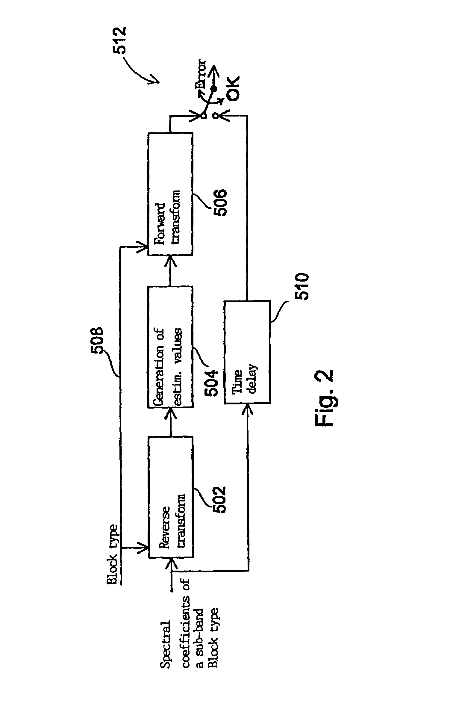
In a method for concealing an error in an encoded audio signal a set of spectral coefficients is subdivided into at least two sub-bands (14), whereupon the sub-bands are subjected to a re-verse transform (16). A specific prediction is performed (18) for each quasi time signal of a sub-band to obtain an estimated temporal representation for a sub-band of a set of spectral coefficients following the current set. A forward transform (20) of the time signal of each sub-band provides estimated spectral coefficients which can be used (28) instead of erroneous spectral coefficients of a following set of spectral coefficients, e.g. in order to conceal transmission errors. Transforming at the sub-band level provides independence from transform characteristics such as block length, window type and MDCT algorithm while at the same time preserving spectral processing for error concealment. Thus the spectral characteristics of audio signals can also be taken into account during error concealment.

Description

FIELD OF THE INVENTION[0001]The present invention relates to the encoding and decoding of audio signals and in particular to error concealment in digital encoded audio signals.BACKGROUND OF THE INVENTION AND PRIOR ART[0002]As a result of the increasingly widespread use of modern audio encoders and the corresponding audio decoders, which operate according to one of the MPEG standards, the transmission of encoded audio signals over radio networks or line-based net-works such as the internet has already become very important. The transmission channel involved in the transmission of encoded audio signals by means of digital radio or over line-based networks is not ideal, which can result in encoded audio signals being adversely affected during the transmission. The decoder is therefore confronted with the question of how to deal with transmission errors, i.e. how these transmission errors are to be “concealed”. The objective of error concealment is to manipulate transmission errors in s...

Claims


Application Information

Patent Timeline
Patent Type & Authority Patents(United States)
IPC IPC(8): G10L19/00G10L13/00G10L19/005H03M7/30H03M7/40
CPCG10L19/005
Inventor LAUBER, PIERREDIETZ, MARTINHERRE, JUERGENBOEHM, REINHOLDSPERSCHNEIDER, RALPHHOMM, DANIEL
Owner FRAUNHOFER GESELLSCHAFT ZUR FOERDERUNG DER ANGEWANDTEN FORSCHUNG EV
Why Eureka
Eureka Blog
Learn More