
Image processing technique for images projected by projector

a technology of image processing and projector, applied in the field of image processing technique applied to images projected by projectors, can solve the problems of insufficient improvement of optical systems, out of focus of projected images at such sites, blurred, etc., and achieve the effect of preventing deterioration of image quality

Active Publication Date: 2006-02-21
IBIDEN CO LTD +1
View PDF30 Cites 20 Cited by
  • Summary
  • Abstract
  • Description
  • Claims
  • Application Information

AI Technical Summary

Benefits of technology

The present invention provides an image processing apparatus that prevents deterioration of image quality due to out-of-focus state in an image projected by a projector. The apparatus carries out image processing with original image data by emphasizing the articulation of display with a varying degree of emphasis at each site of the projected image. The degree of emphasis is determined based on the out-of-focus degree at each site. The apparatus can use sharpness adjustment or luminance adjustment as the specific image processing to emphasize the articulation of display. The degree of emphasis can be varied based on the distance from the reference point set relative to the projected image. The apparatus can also automatically detect the focalized position of the projected image and use it as the reference point. The compensation coefficient storage module stores in advance a mapping of a compensation coefficient to each site, which is used for emphasizing the articulation of display. Overall, the invention provides a technique for preventing deterioration of image quality without optical adjustment of the focal distance at each site.

Problems solved by technology

The projected image at such sites is out of focus and rather blurred.
Any improvement of the optical system can not sufficiently solve this problem.

Method used


Image

  • Image processing technique for images projected by projector
  • Image processing technique for images projected by projector
  • Image processing technique for images projected by projector

Examples


modified example 1

D1. Modified Example 1

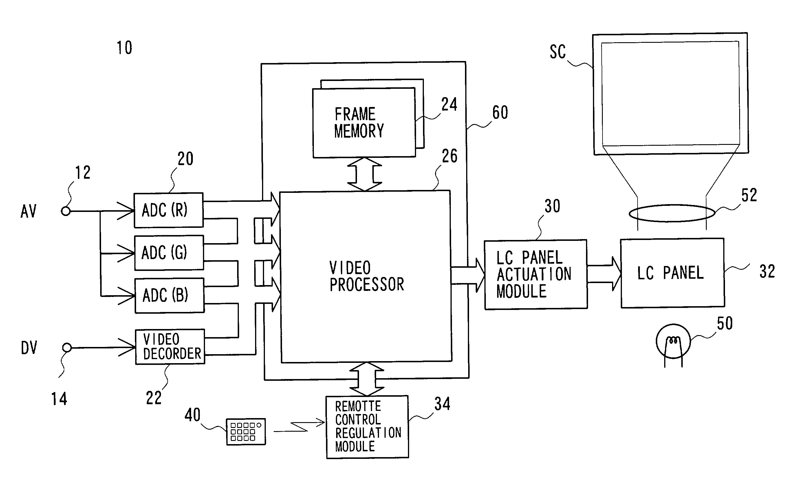
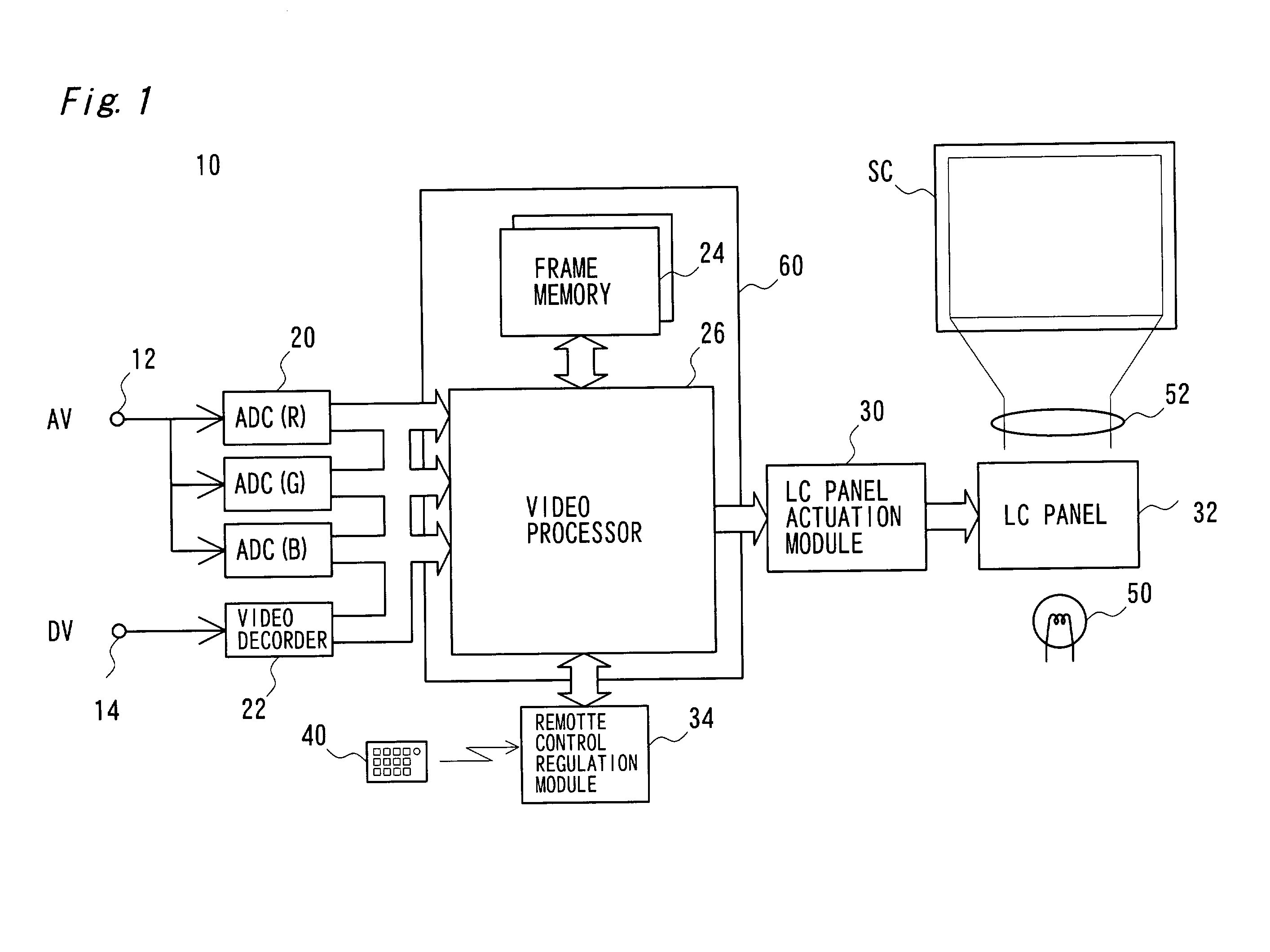
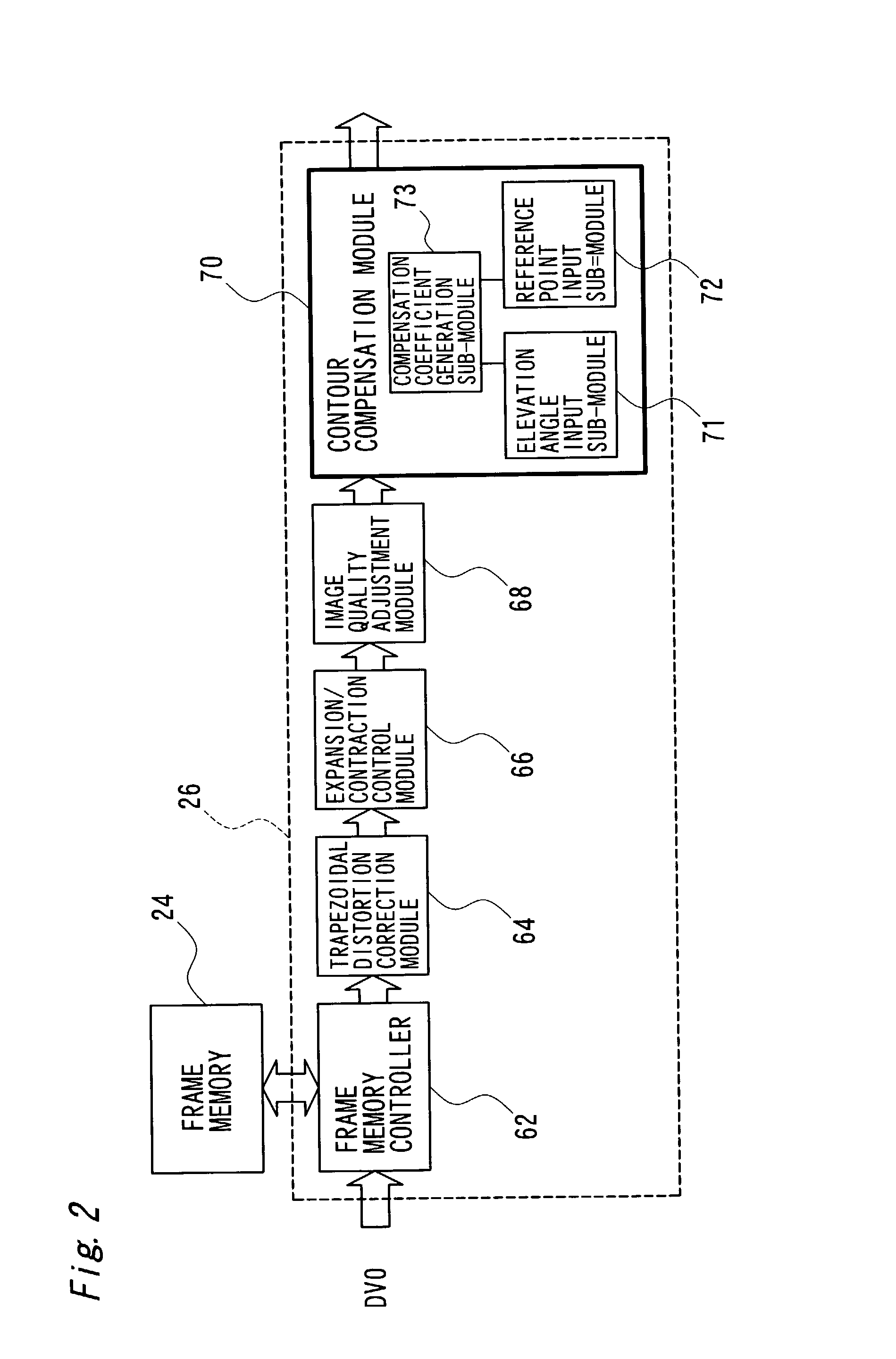
[0079]FIG. 10 is a block diagram illustrating the structure of a contour compensation module 70A in another projector 10A as a modified example. The projector 10A has an elevation angle detection module 78 and a reference point detection module 79, in addition to the constituents of the projector 10 of the above embodiment. The contour compensation module 70A is connected to these modules 78 and 79. The elevation angle detection module 78 measures distances to preset three points on the screen SC with an ultrasonic sensor, and automatically detects the vertical component and the horizontal component of the elevation angle based on the measurement result. Another means may alternatively be used to detect the vertical component and the horizontal component of the elevation angle. The detection result of the elevation angle detection module 78 is input into the elevation angle input sub-module 71 (see FIG. 2). The reference point detection module 79 includes an im...

modified example 2

D2. Modified Example 2

[0080]The procedure of the above embodiment carries out the sharpness adjustment with the varying degree of emphasis for the respective pixels. One modified procedure may carry out the sharpness adjustment with the varying degree of emphasis for the respective image areas. For example, an identical compensation coefficient is applied for each 8×8 block (image area) in the image, and the sharpness adjustment is carried out with compensation coefficients corresponding to the distances between the reference point and the centers of the respective blocks.

modified example 3

D3. Modified Example 3

[0081]The procedure of the above embodiment carries out the sharpness adjustment with the varying degree of emphasis for the respective pixels. In general, the present invention performs image processing to emphasize the articulation of the display with different degrees of emphasis for the respective sites of the image projected by the projector. The image processing is thus not restricted to the sharpness adjustment but may be any adjustment affecting the articulation of the display, for example, contrast adjustment or luminance adjustment, at each site of the projected image.


PUM

PropertyMeasurementUnit
distanceaaaaaaaaaa
angleaaaaaaaaaa
elevation angle detectionaaaaaaaaaa

Abstract

The technique of the present invention carries out specific image processing that emphasizes articulation of display with a varying degree of emphasis for respective sites of an image projected by a projector. A typical example of such image processing is sharpness adjustment. The degree of emphasis in sharpness adjustment at each site is specified, based on an elevation angle of the projector and a focalized position of the projected image. The technique of the invention thus readily prevents deterioration of the image quality due to out-of-focus state of the projected image.

Description

BACKGROUND OF THE INVENTION[0001]1. Field of the Invention[0002]The present invention relates to an image processing technique applied for images projected by a projector.[0003]2. Description of the Related Art[0004]A projector modulates light emitted from a light source based on image data with its light modulation means, such as a liquid crystal panel, and displays a resulting image on a screen. ‘Elevated projection’ is often adopted to prevent any obstacle between the projector and the screen from interfering with the view of the projected image.[0005]FIG. 11 shows projection of an image on a screen SC with a prior art projector 100. In the example of FIG. 11A, an elevation angle, that is, an angle defined by an optical axis of the projector 100 and a normal line of the screen SC, is equal to 0. A resulting projected image P is rectangle without any significant distortion. In the example of FIG. 11B, the elevation angle is θ (≠0). A resulting projected image P′ has trapezoidal di...

Claims


Application Information

Patent Timeline
Patent Type & Authority Patents(United States)
IPC IPC(8): G06K9/00G03B21/00H04N5/64G02F1/13G03B21/14G06T5/00H04N5/208H04N5/74H04N17/00
CPCG06T5/006H04N5/208H04N9/3194H04N9/3185H04N5/74G06T5/80
Inventor TAKEUCHI, KESATOSHINAKAMURA, KAZUYOSHI
Owner IBIDEN CO LTD
Learn More