
High reliability forensic color marking system

a color printing system and high reliability technology, applied in the field of color printing systems, can solve the problems of difficult to distinguish from the original, high cost, and undesired copying of proprietary or confidential business documents, and achieve the effect of high degree of accuracy

Inactive Publication Date: 2006-02-21
HEWLETT PACKARD DEV CO LP
View PDF30 Cites 41 Cited by
  • Summary
  • Abstract
  • Description
  • Claims
  • Application Information

AI Technical Summary

Benefits of technology

[0008]In a preferred embodiment, the present invention provides a forensic marking system that unobtrusively marks printed media with encoded system information which subsequently allows the system on which the media were printed to be identified from the media with a high degree of accuracy, even where the markings are superimposed on other image content on the media. Such a marking system serves as a deterrent to counterfeiting of valuable documents by allowing the counterfeited materials to be traced back to their source.
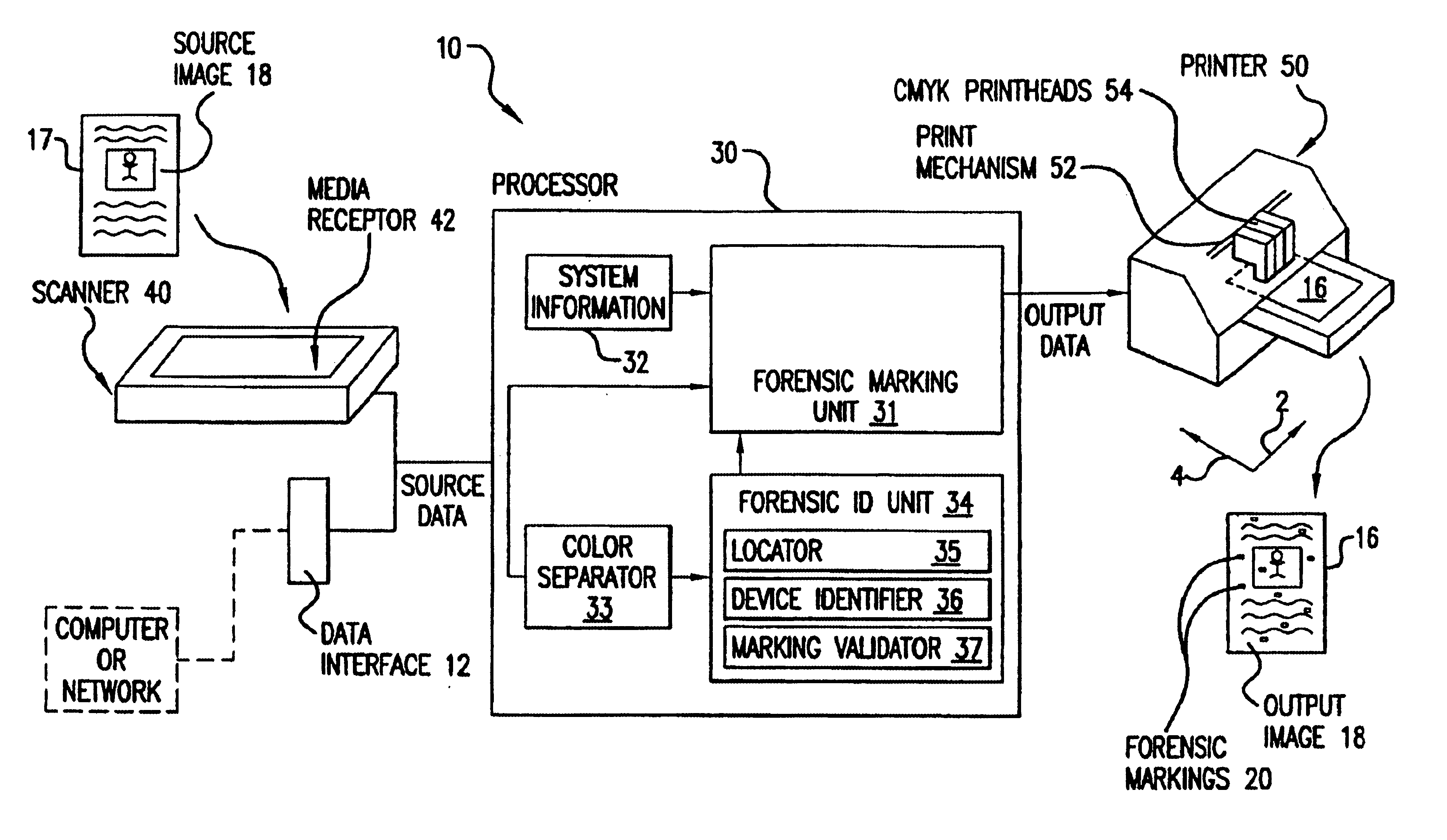
[0009]The preferred forensic marking system has a processor which superimposes onto source data representing the image to be printed at least one forensic marking. The source data may be provided to the marking system in electronic form from a data interface coupled to the processor. In some embodiments, the forensic marking system may also include a scanner coupled to the processor for acquiring the electronic source data by optically scanning a source image contained on a printed medium. The forensic marking contains an information marker which identifies the system, and an checksum marker which validates the integrity of the information marker. The system also includes a printer coupled to the processor which receives the combined source data and forensic markings, and prints each forensic marking on the resulting image using a predetermined color which has a low visual response to the human eye, but which is readily detectable by electronic scanning so that the system on which the marked image was printed can be accurately identified, even where a portion of the source data and a portion of a forensic marking are printed in the same image pixels. The marking system of the preferred embodiment prints images using cyan, magenta, and yellow colorant, with the forensic markings superimposed in yellow. The forensic marking may also include at least one location marker which locates the forensic marking on the printed medium. The rectangular forensic marking of the preferred embodiment uses two location markers, a first location marker located at one corner of the marking, and a second location marker different from the first location marker located at the diagonally opposite corner of the marking. In some embodiments, the forensic marking may additionally include at least one camouflage marker containing a randomized data pattern in order to reduce the perceptibility of the forensic marking where it is replicated in multiple locations on the printed medium. The perceptibility of the forensic markings may additionally be reduced by rotating some of the markings on the medium by a multiple of 90 degrees. In the preferred embodiment, the rectangular array of the forensic marking is a sixty-four pixel by sixty-four pixel matrix, which is organized into sixty-four eight pixel by eight pixel cells. Colorant for the forensic marking is deposited during printing in at most one pixel of each of the eight pixel by eight pixel cells. This results in a maximum print density of the forensic marking within the rectangular array of approximately 1.5 percent, which avoids any significantly degradation of the image quality. In the preferred embodiment, the forensic marking is replicated on the printed medium at 256 pixel-row and pixel-column intervals. In addition, adjacent forensic markings are offset from each other by a one pixel-row.

Problems solved by technology

When an optical scanner is used in combination with a printer and the appropriate print media, original documents can be scanned and printed to produce copies which can be difficult to distinguish from the original.
A related concern is the undesired copying of proprietary or confidential business documents intended for only limited distribution.
As a result, they tend to be expensive, in part because accurate determination of prohibited versus acceptable originals is difficult, and also because the system must be programmed to recognize each type of document intended to be protected.
Such systems tend to be less complex in part because they do not attempt to prevent the copying of certain documents, but rather imprint all copies they produce with additional forensic information.
However, since it is likely that most printed copies produced by the system will be of perfectly legitimate documents, it is highly desirable that the forensic information be virtually unnoticeable to the unaided human eye, in order to avoid undesirably degrading the print quality of the copy.
However, when the print density of a page is sufficiently high, such as when a photographic image is printed, there may not be enough remaining blank space to accommodate sufficient forensic markings to ensure accurate recognition.
However, since the image itself may already contain yellow image content, forensic markings overlaid in these regions may be corrupted to such a degree that they misidentify the copying device, unless a mechanism exists to validate the markings.

Method used


Image

  • High reliability forensic color marking system
  • High reliability forensic color marking system
  • High reliability forensic color marking system

Examples


Embodiment Construction

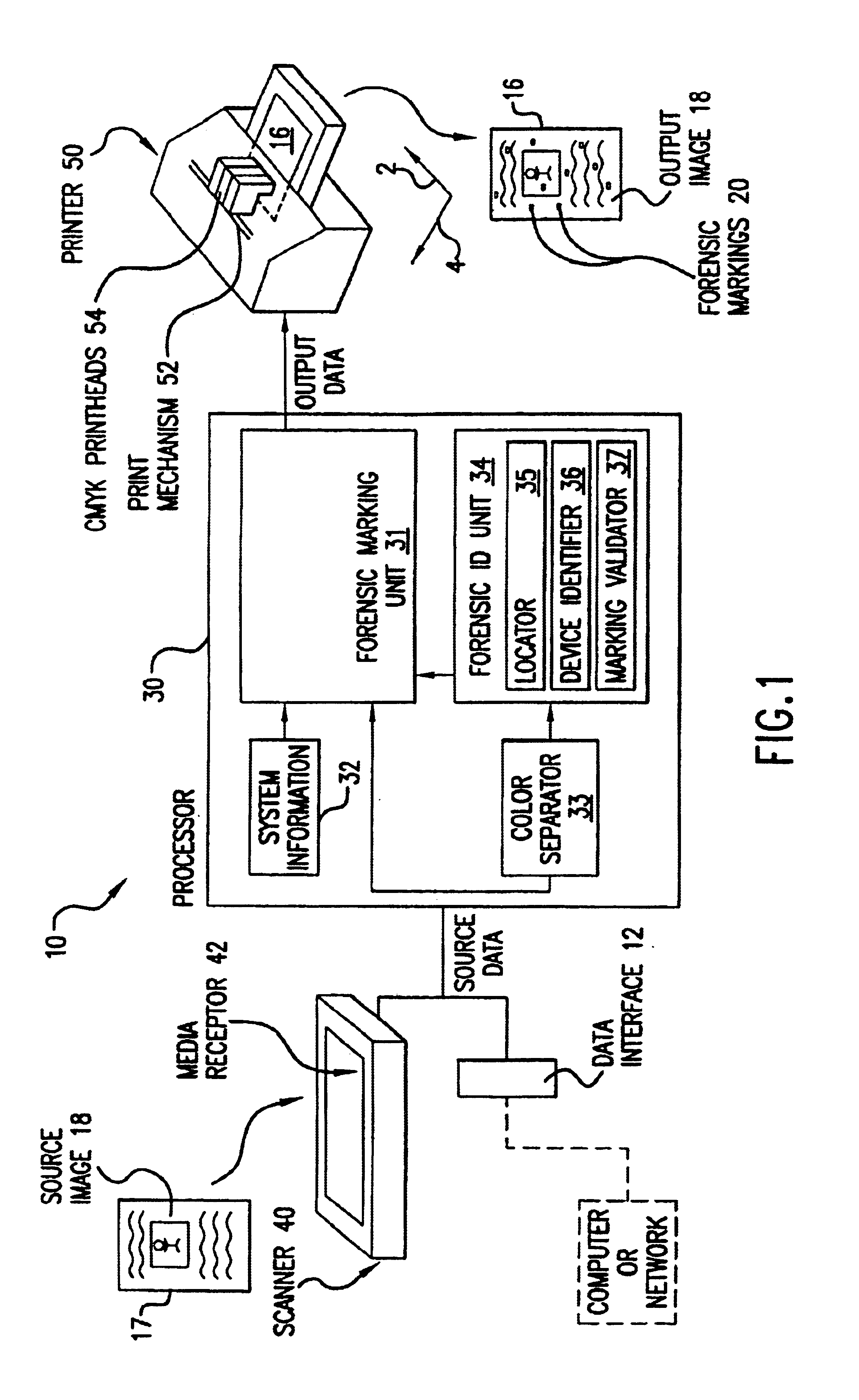
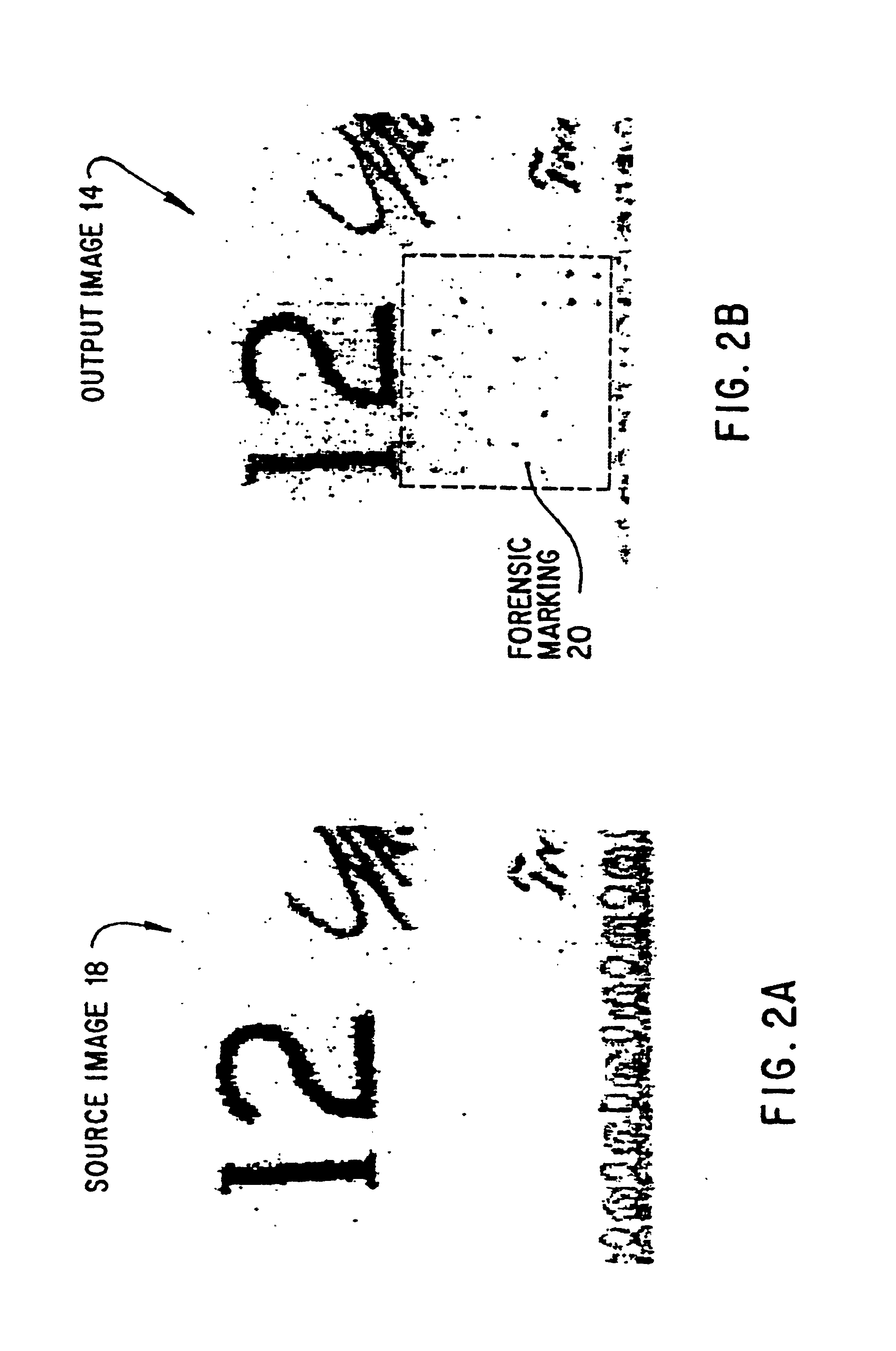
[0026]Referring now to the drawings, and more particularly to FIGS. 1, 2A, and 2B, there is illustrated a passive marking printing system 10 constructed in accordance with the present invention which adds to output images 14 printed on a medium 16 encoded forensic markings 20 capable of identifying the printing system 10. The system 10 advantageously minimizes the impact of these forensic markings 20 on print quality by marking the printed medium 16 with a small amount of imperceptible information overlaid on the image content, while ensuring that the system 10 that produced the printed medium 16 can be identified with a high degree of accuracy from the forensic markings 20 on the printed medium 16.

[0027]A preferred embodiment of the printing system 10 includes a processor 30 for superimposing onto source data at least one forensic marking 20 having an encoded pattern of image pixels in graphical form so as to create output data corresponding to the forensically marked output image ...


PUM


Abstract

A forensic marking system and method for identifying the printing device on which a medium was printed. Encoded forensic markings which identify the device but are of low perceptibility to the human eye are superimposed on the printed image. The markings have a color, size, density, and repetition pattern that only minimally affect print quality while providing highly accurate identification of the printing device, even if the printed medium contains high-density image content.

Description

FIELD OF THE INVENTION[0001]The present invention relates generally to printing with color printing systems. It relates more particularly to a forensic marking system for color printers that accurately identifies the printer on which the output was printed, while minimizing the perceptibility of the forensic markings to the human eye.BACKGROUND OF THE INVENTION[0002]Over the past several years, the quality of color images produced by computer printers such as inkjet printers and color laser printers has improved to the point where such images now rival those achievable through color photography. In addition, many such printers are capable of printing on a wide range of media, including paper stocks of various qualities, sizes and thicknesses. When an optical scanner is used in combination with a printer and the appropriate print media, original documents can be scanned and printed to produce copies which can be difficult to distinguish from the original. The scanner can be a separat...

Claims


Application Information

Patent Timeline
Patent Type & Authority Patents(United States)
IPC IPC(8): G06K15/00G06F3/12G06K15/02H04N1/40B41M3/14G07D7/12G07D7/20
CPCB41M3/14G07D7/20G07D7/12H04N2201/323G07D7/004G06F3/12
Inventor VAN LIEW, EDWARD JNATHAN, NOBUKO MULUPINAR, BIRSEN
Owner HEWLETT PACKARD DEV CO LP
Learn More