
Method for driving active matrix type liquid crystal display

a liquid crystal display and active matrix technology, applied in the direction of electric digital data processing, instruments, computing, etc., can solve the problem that the voltage applied to the liquid crystal cannot be significantly reduced, and achieve the effect of preventing the degradation of the display data output switch, reducing the voltage drive, and increasing the density

Inactive Publication Date: 2006-02-21
SANYO ELECTRIC CO LTD
View PDF15 Cites 8 Cited by
  • Summary
  • Abstract
  • Description
  • Claims
  • Application Information

AI Technical Summary

Benefits of technology

[0007]The present invention was conceived to solve at least the problem mentioned above, and one object of the present invention is to provide an active matrix type liquid crystal display in which the power consumption is reduced and, at the same time, necessary and sufficient voltage can be applied to the liquid crystals.
[0012]With the recent trend for higher density mounting and lower voltage drive of liquid crystal display devices, the size and peak inverse voltage of the switching elements employed in the drive circuit of the display are becoming smaller. This trend also applies to the display data output switches for outputting display data to the data lines, which are provided between the display data source and the data lines. Therefore, if the potential on the data line is significantly changed because of the change in the opposing electrode potential, a large reverse bias will be loaded to the output switch, possibly causing disadvantages such as degradation of the output switches. In the present invention, on the other hand, even though the opposing electrode voltage is changed, the potential change on the data lines caused by the change in the opposing electrode potential is inhibited by applying a change alleviating voltage to the data lines when the opposing electrode voltage changes. Thus, it is possible to prevent the degradation of the display data output switches as described above.
[0013]Also, in the present invention, the change alleviating voltage is at the center voltage of the display data. With such a configuration, the degradation of the display data output switch can be reliably prevented without increasing the circuit loading. Moreover, because the polarity, with respect to the center voltage, of the display data which is output to the data lines is periodically inverted in a predetermined period, no delay in the inversion operation is caused and the display quality is not adversely affected, even if the voltage of the data lines is set at the center voltage when the pixels are not selected.
[0014]According to the present invention, in addition to the reduction in the power consumption through inversion of the voltage of the opposing electrode, the voltage change on the data lines when the opposing electrode voltage is changed is also reduced. Therefore, because unnecessary loading to the switches or the like for selecting a data line can be prevented, the possibility of display defects in the column direction can be reduced, display quality can be maintained, and device reliability can be improved.

Problems solved by technology

However, in order to reliably control the alignment of the liquid crystal, application of sufficient voltage to the liquid crystal is desired, and, thus, the applied voltage to the liquid crystal cannot be reduced significantly.

Method used


Image

  • Method for driving active matrix type liquid crystal display
  • Method for driving active matrix type liquid crystal display
  • Method for driving active matrix type liquid crystal display

Examples


Embodiment Construction

[0020]The preferred embodiment of the present invention, hereinafter referred to simply as the embodiment, will now be described referring to the drawings.

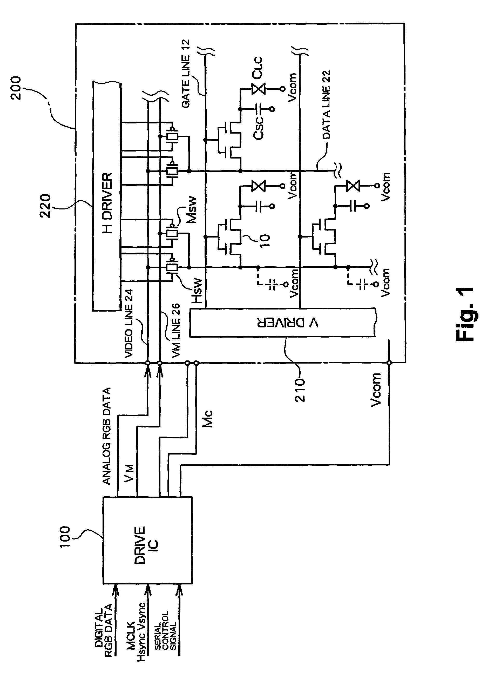
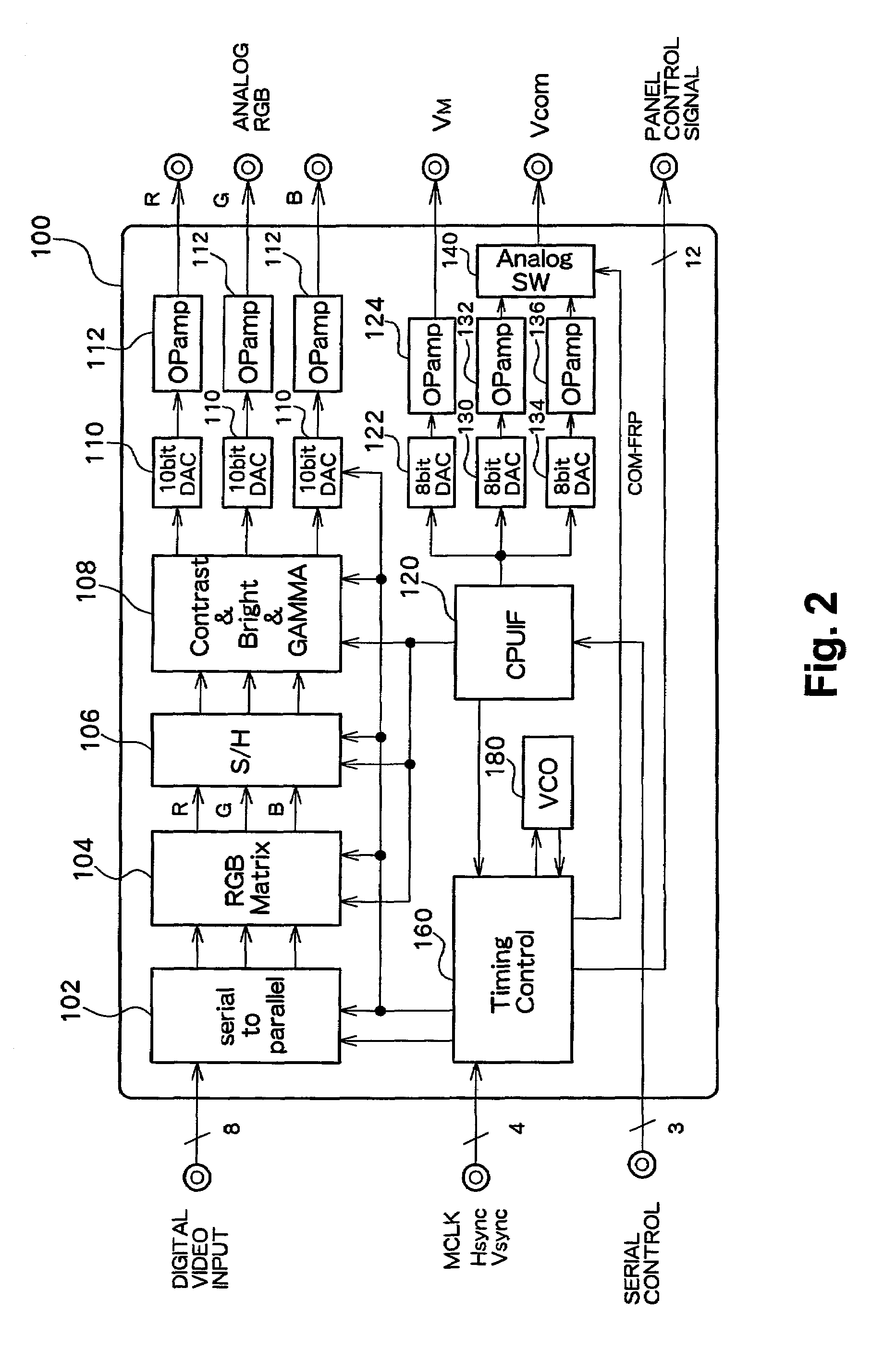
[0021]FIG. 1 shows an overall structure of an active matrix type liquid crystal display according to the embodiment of the present invention. FIG. 2 shows a structure of a drive IC 100 for a display panel.

[0022]A liquid crystal display panel 200 is constructed by affixing a first substrate and a second substrate, each made of, for example, a glass substrate, with a predetermined gap between them and sealing liquid crystal in this gap. In an active matrix type liquid crystal display panel, pixel electrodes which are arranged in a matrix and switching elements 10 (here a TFT having a double gate structure) respectively connected to the pixel electrodes are formed on the first substrate, and, furthermore, selection lines (gate lines) 12 for sequentially selecting the TFTs and data lines 22 for supplying display data to the selected T...


PUM

PropertyMeasurementUnit
timeaaaaaaaaaa
timeaaaaaaaaaa
voltageaaaaaaaaaa

Abstract

In an active matrix type liquid crystal display, during a non-display period such as the horizontal blanking interval or the vertical blanking interval wherein no pixel TFT is selected, the voltage of the opposing electrode is changed so that the power consumption is reduced with application of sufficient voltage to the liquid crystal and without increasing the amplitude of the display data. Also, a change alleviating voltage VM is applied during the change in the opposing electrode voltage to data lines for supplying display data to each of pixel TFTs during the display period, in order to prevent changes in the potential of the data lines caused by the change in the opposing electrode voltage and large reverse bias from being loaded to switches Hsw for outputting display data to the data lines.

Description

BACKGROUND OF THE INVENTION[0001]1. Field of the Invention[0002]The present invention relates to method of driving an active matrix type liquid crystal display, and more particularly to a method of alternating drive of opposing electrodes in active matrix type liquid crystal displays.[0003]2. Description of the Related Art[0004]An active matrix type liquid crystal display (LCD) comprises a switch element such as a thin film transistor (hereinafter referred to as a “TFT”) in each pixel, and display data is supplied to each pixel electrode via the switch element so that the alignment of liquid crystal in each pixel is controlled by the pixel electrode and an opposing electrode (common electrode) provided to oppose the pixel electrode with the liquid crystal in between.[0005]Although a liquid crystal display inherently has a low power consumption, further reduction in the power consumption is strongly demanded in portable information devices or the like to which LCD displays are equipp...

Claims


Application Information

Patent Timeline
Patent Type & Authority Patents(United States)
IPC IPC(8): G09G3/28G02F1/133G09G3/20G09G3/36
CPCG09G3/3648G09G3/3614G09G2320/02G09G3/3688G09G2310/0248G09G3/3655G09G3/36
Inventor MIYAJIMA, YASUSHIYOKOYAMA, RYOICHI
Owner SANYO ELECTRIC CO LTD
Learn More