
Radiation device

Inactive Publication Date: 2006-02-21
ARCCURE TECH
View PDF9 Cites 9 Cited by
  • Summary
  • Abstract
  • Description
  • Claims
  • Application Information

AI Technical Summary

Benefits of technology

[0011]It is thus the object of the invention to create an irradiation device, in particular a UV irradiation device which allows larger irradiation widths without there being any deformation of the radiation source.

Problems solved by technology

As a result of this, the upper side may be subjected to local overheating which can destroy the radiation source.

Method used


Image

  • Radiation device
  • Radiation device
  • Radiation device

Examples


Embodiment Construction

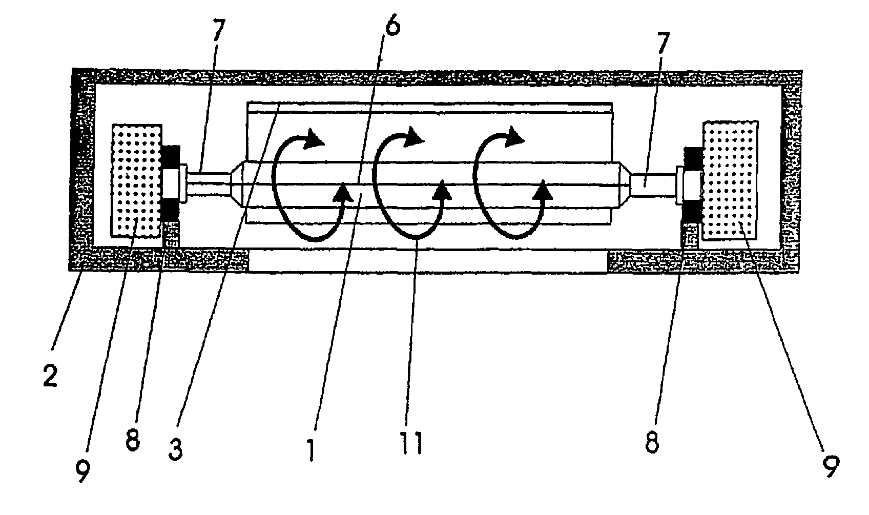
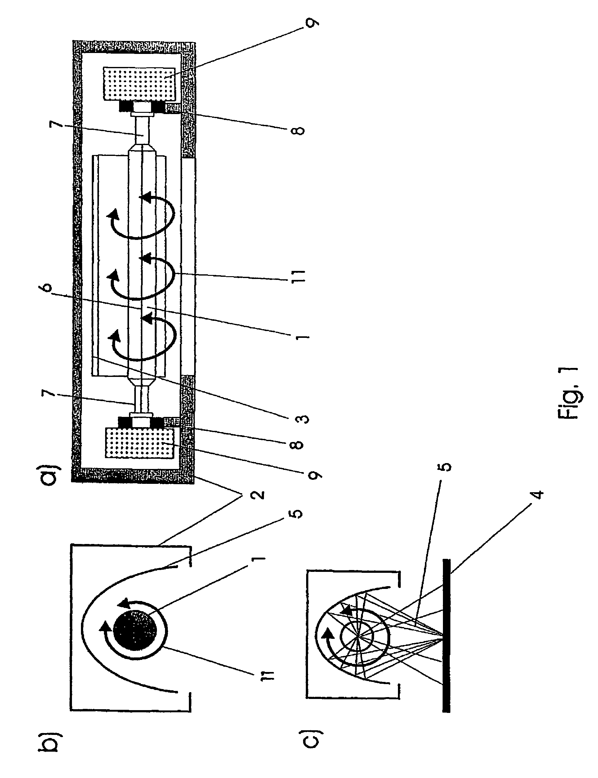
[0034]FIG. 1a) shows a tubular elongated radiation source 1 which is arranged within a housing 2 between a reflector 3 and the object 4 to be irradiated. The path of the rays 5 shown in FIG. 1c) leads to the object 4, partly directly from the radiation source 1, and partly indirectly by way of the reflector 3. The radiation source 1 is arranged in the housing 2 of the irradiation device such that it is rotatable on its longitudinal axis 6. The ends 7 of the radiation source are held by seat arrangements 8 which are held so as to be rotatable. The driving force for rotating the radiation source 1 is provided by the two drives 9 and the gear arrangement (not shown in detail) arranged therein. The direction of rotation of the radiation source, which direction is indicated by the arrow 11 in FIGS. 1a)–c) can be changed by means of a reversing-control system (not shown) which is known per se.

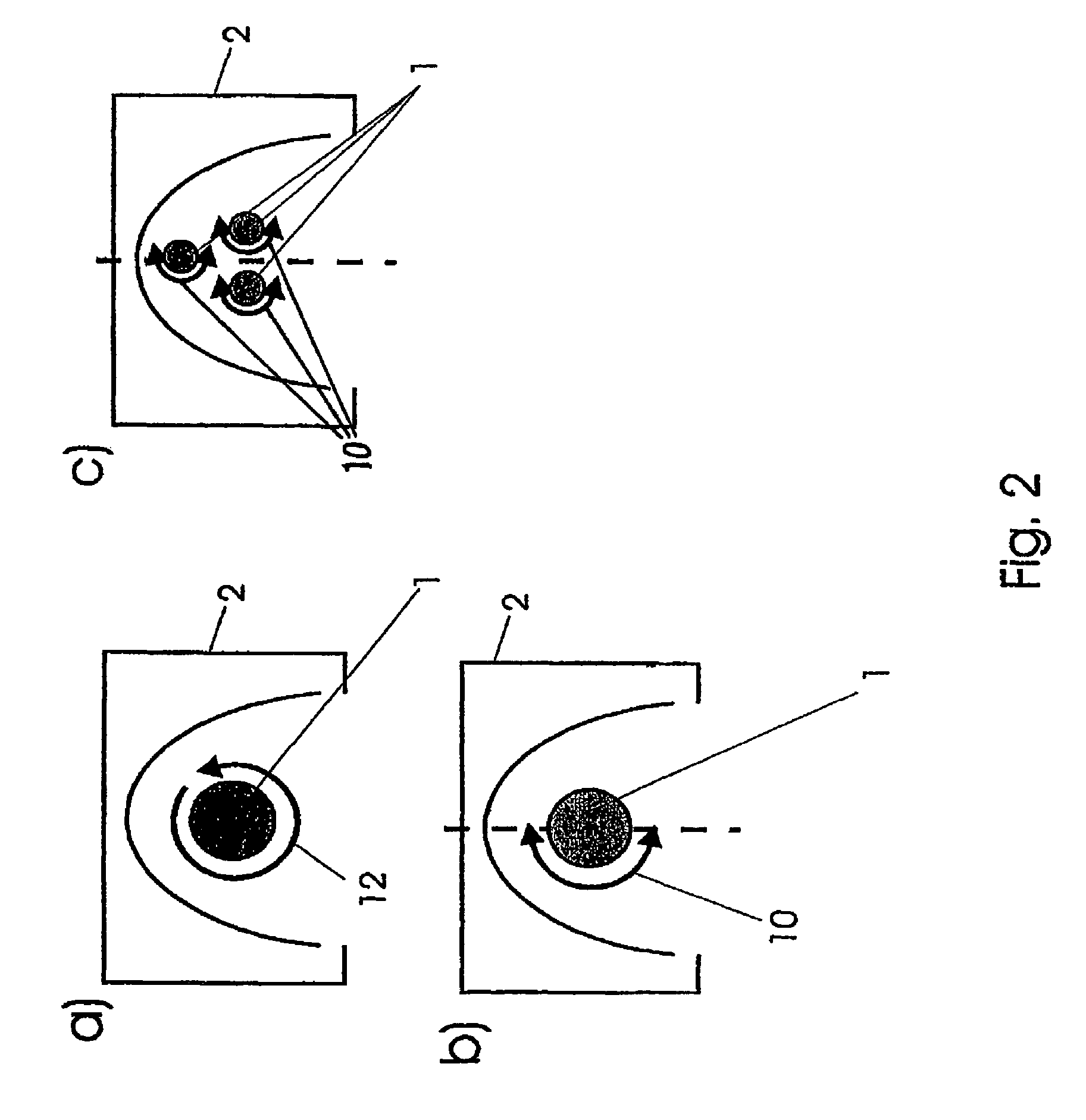
[0035]FIGS. 2a, b show different operating modes of the irradiation device according to FIG. 1. I...


PUM

PropertyMeasurementUnit
Angleaaaaaaaaaa
Speedaaaaaaaaaa

Abstract

The invention relates to an irradiation device for irradiating objects, comprising a housing having an outlet for the electromagnetic radiation directed at an object to be irradiated and at least one long radiation source for the electromagnetic radiation arranged in the housing. In order to enable bigger irradiation widths in an irradiation device, more particularly in a UV irradiation device, without deformation of the radiation source, at least one of the radiation sources in the irradiation device is rotationally arranged about its longitudinal axis.

Description

PRIORITY CLAIM[0001]This is a U.S. national stage of application No. PCT / EP02 / 05519, filed on 18 May 2002. Priority is claimed on that application and on the following application: Country: Germany, Application No.: 101 25 770.8, Filed: 26 May 2001.BACKGROUND OF THE INVENTION[0002]1. Field of the Invention[0003]The invention relates to an irradiation device for irradiating objects, in particular with ultraviolet and / or infrared and / or visible electromagnetic radiation, comprising a housing which comprises an outlet aperture for electromagnetic radiation, which outlet aperture is aligned to the object to be irradiated, as well as comprising at least one elongated radiation source, arranged in the housing, for electromagnetic radiation. Furthermore, the invention relates to an operating system for a radiation source according to the invention.[0004]2. Description of the Related Art[0005]Irradiation devices, in particular for UV light, are used for photochemically influencing irradiate...

Claims


Application Information

Patent Timeline
IPC IPC(8): H05B31/04B41F23/04A61L2/08A61L2/10A61N5/06B01J19/12B05C9/12B05D3/06B29C71/04G21K1/00G21K5/00G21K5/04
CPCA61L2/08G21K5/04B05D3/067A61L2/10
Inventor SCHWEITZER, BERT
Owner ARCCURE TECH
Learn More