
Clip control system for walk reel mower

Active Publication Date: 2011-08-04
TORO CO THE
View PDF21 Cites 1 Cited by
  • Summary
  • Abstract
  • Description
  • Claims
  • Application Information

AI Technical Summary

Benefits of technology

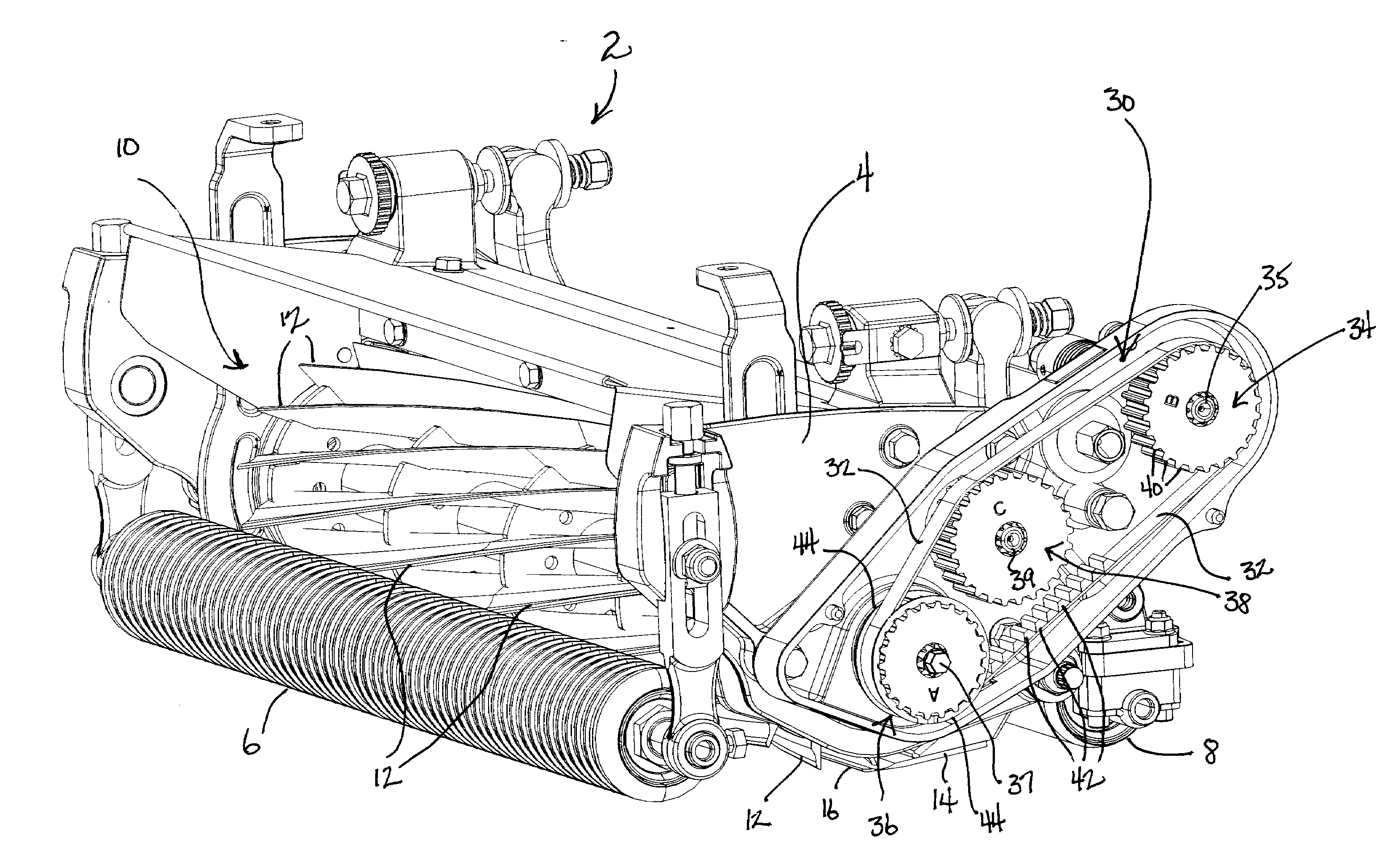
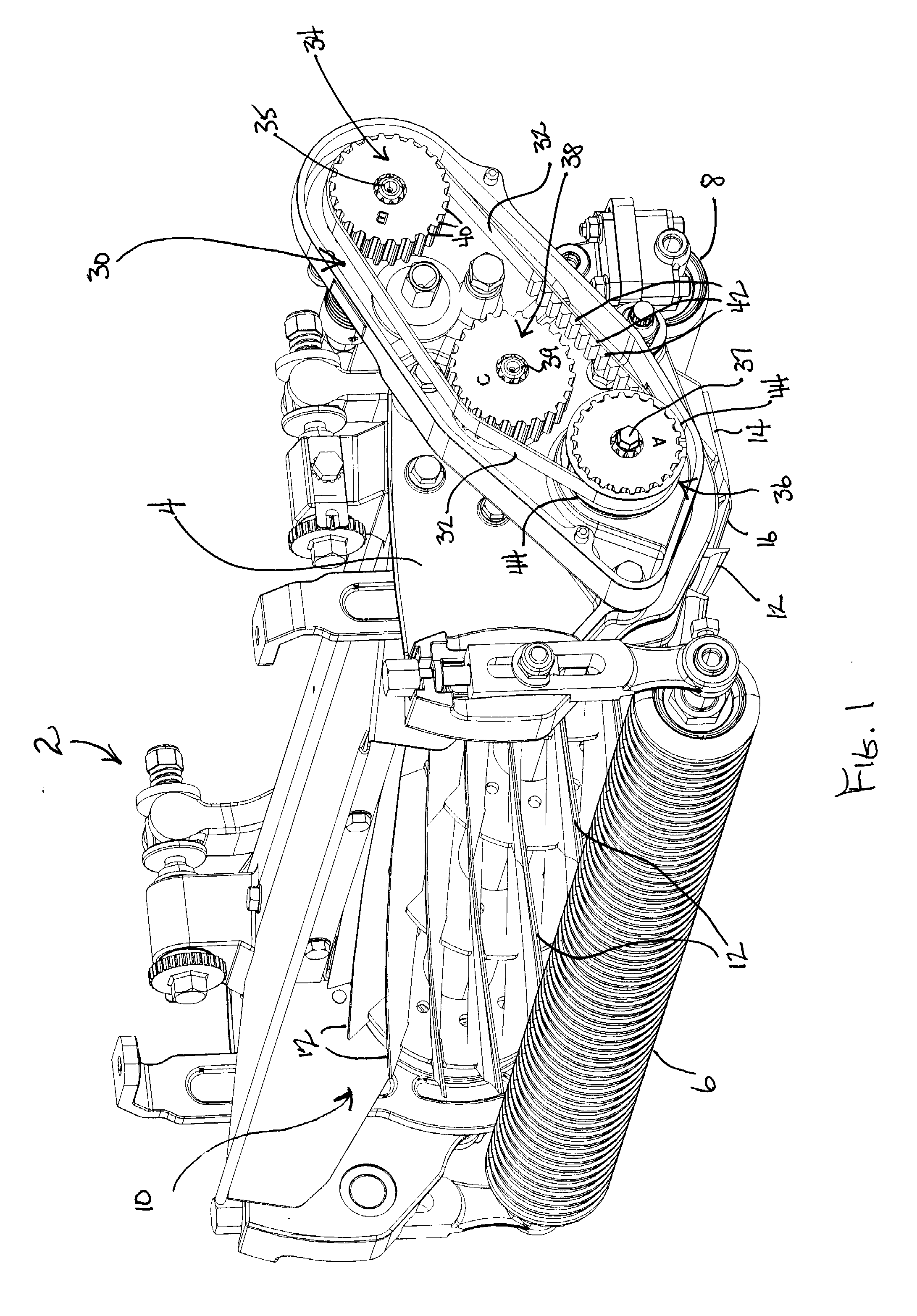
[0007]One aspect of this invention relates to a reel cutting unit which comprises a reel having a plurality of transversely extending blades that are spaced apart around a circumference of the reel, the reel being rotatable about a substantially horizontal axis. A bedknife is located adjacent the reel and is cooperable with the reel to cut grass as the blades of the reel sweeps uncut grass against a cutting edge on the bedknife. The rotation of the reel produces a clip that comprises a forward distance of travel of the cutting unit in a time interval determined by the length of time that it takes for successive blades on the reel to contact a predetermined reference spot on the bedknife. A clip control and selection system is provided for selecting one of a predetermined number of different possible clips when the reel cutting unit is propelled over the ground at a substantially constant ground speed. The clip control and selection system comprises a drive shaft, a driven shaft, and an idler shaft that mount, respectively, a circular drive member, a circular driven member, and a circular idler member, each of the circular members having a different diameter from the other circular members. A flexible and endless transmission member is entrained around the drive and driven members to transfer rotation of the drive shaft to the driven shaft with the driven shaft being operatively connected to the reel to rotate the reel. The idler member also engages with the endless transmission member. The drive, driven and idler shafts are sufficiently similar in outside diameter to one another, and the drive, driven and idler members have mounting bores that are sufficiently similar in inside diameter to one another, that any of the drive, driven and idler members can be interchangeably mounted at any given time on any of the drive, driven and idler shafts to provide six different possible clips, or drive ratios, for selection by a user for a given constant rotational input speed of the drive shaft.
[0008]Another aspect of this invention relates to a method of controlling and selecting clip in a reel cutting unit having a reel with a plurality of circumferentially spaced blades that are cooperable with a bedknife to cut grass therebetween, the clip comprising a forward distance of travel of the reel cutting unit over the ground in a time interval determined by the length of time that it takes for successive blades on th

Problems solved by technology

However, this provides a very limited number of different clips, namely two depending upon which of the different drive pulleys is in place.
If one of the alternately usable drive pulleys is lost or can't be found, the clip can't be changed.

Method used


Image

  • Clip control system for walk reel mower
  • Clip control system for walk reel mower

Examples


Embodiment Construction

[0011]Referring first to FIG. 1, an improved reel cutting unit of this invention is generally as 2. Cutting unit 2 includes a cutting unit frame 4 that is supported for rolling over the ground by a grooved front roller 6 and a smooth rear roller 8. Cutting unit 2 includes a transversely extending reel 10 having a number of transversely extending, helically twisted blades 12 circumferentially spaced around the circumference of reel 10. Blades 12 cooperate with a fixed bedknife 14 on cutting unit frame 4. During the rotation of reel 10 about its horizontal axis of rotation, the successive blades 12 on reel 10 sweep the standing and uncut grass against a sharpened front cutting edge 16 of bedknife 14 to sever the grass in a shearing type action.

[0012]U.S. Pat. No. 6,622,464 is assigned to The Toro Company, the assignee of this invention, and is hereby incorporated by reference. The 464 patent discloses a walk reel mower of the type on which cutting unit 2 shown in FIG. 1 may be mounted...


PUM


Abstract

A reel cutting unit of a reel mower is provided with a belt and pulley drive system for rotating the reel of the cutting unit at variable speeds when the ground speed of the reel cutting unit is substantially constant to provide different clips. The drive system has three pulleys of different diameter in engagement with the belt in drive, driven and idler positions. The pulleys can be interchangeably used in any of the positions by moving the pulleys around into the different positions in six different possible arrangements. The pulleys are selectively placed in one arrangement at a time to select the clip provided by that arrangement. A chain and sprocket drive system with different diameter sprockets may be used in place of the belt and pulley drive system. The belt and pulley drive system may comprise toothed pulleys and toothed timing belt.

Description

CROSS REFERENCE TO RELATED APPLICATIONS[0001]This application claims the benefit of one or more previously filed copending provisional applications identified as follows: Application Ser. No. 61 / 301,448 filed Feb. 4, 2010.TECHNICAL FIELD[0002]This invention relates to a walk reel mower that cuts grass while traveling over the ground at a substantially constant mowing speed. More particularly, this invention relates to a system and method for conveniently controlling and changing the clip of the mower.BACKGROUND OF THE INVENTION[0003]The term “clip” in the mowing art refers to a characteristic of the operation of a reel cutting unit, namely the amount of forward travel of cutting unit 2 in the time interval determined by the length of time that it takes for successive blades on the cutting reel to contact a predetermined reference spot on the bedknife. The cutting reel has a number of helically twisted blades spaced about its circumference. As the cutting reel rotates at a substantia...

Claims


Application Information

Patent Timeline
IPC IPC(8): A01D34/00F16H7/02F16H7/06A01D34/53
CPCA01D34/00F16H7/06F16H7/02A01D34/53A01D34/62A01D34/52
Inventor PATTON, ROBERT D.
Owner TORO CO THE
Learn More