
Zinc/air cell

Active Publication Date: 2006-02-21
DURACELL U S OPERATIONS
View PDF16 Cites 36 Cited by
  • Summary
  • Abstract
  • Description
  • Claims
  • Application Information

AI Technical Summary

Benefits of technology

The invention is about improving the assembly process for zinc / air cells, specifically miniature zinc / air cells in the form of button cells. The assembly process involves filling the anode and cathode casings with active material and necessary internal components, and then crimping the edges of the casings together. The crimping step causes a tight interference fit between the two casings, which ensures a tight seal without any deformation of the casings. The invention also provides an improved method for creating the crimped edge, which involves using an annular punch to force the casings together and create the crimp. The overall effect of the invention is to simplify the assembly process for zinc / air cells and improve their reliability.

Problems solved by technology

This causes the cathode disk to expand radially resulting in a tight interference fit between the cathode disk and inside surface of the cathode casing side walls.

Method used


Image

  • Zinc/air cell
  • Zinc/air cell
  • Zinc/air cell

Examples


example 1

Anode and Cathode Casing Wall Thickness 4 mil (0.102 mm)

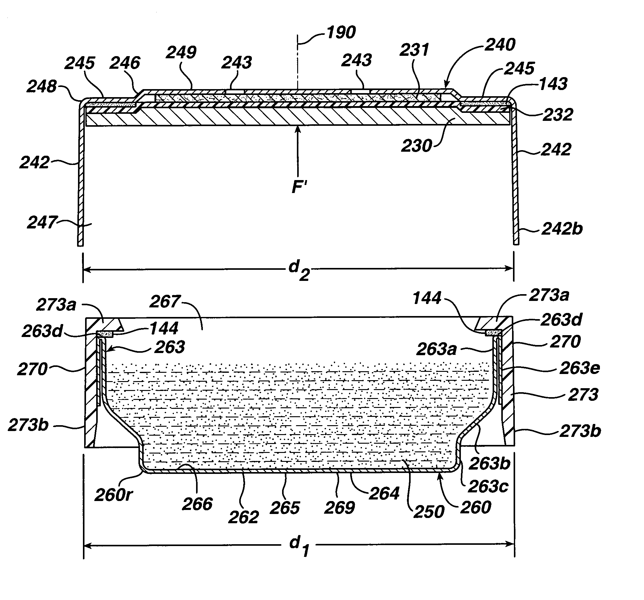
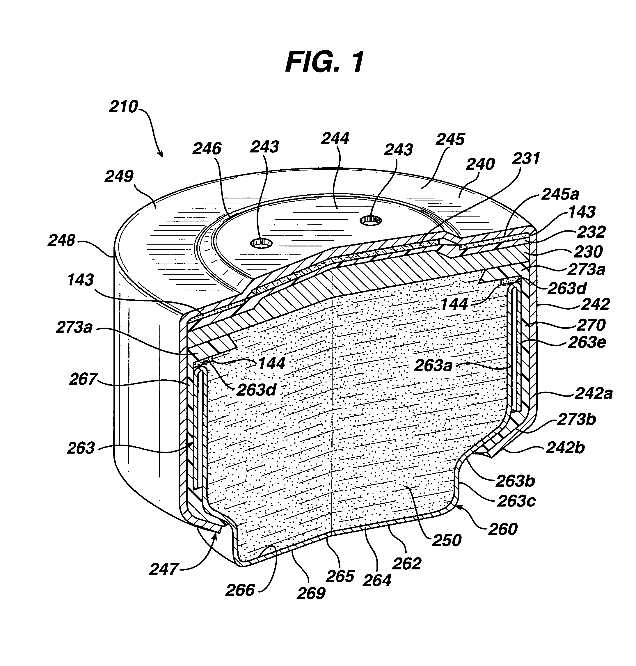
[0063]A zinc / air cell having overall dimensions approximately 8 mm diameter and 4 mm thick (Duracell 312 size) was fabricated according to the process of the invention. The anode casing 260 and cathode casing 240 of the completed cell had a small wall thickness of 4 mil (0.102 mm). The anode casing had a folded (double) side wall comprising an inner portion 263a and an outer portion 263e. Insulator seal 270 had a side wall thickness of 6.5 mil (0.165 mm). The cathode disk 233 had an overall diameter which was 2.0 mil (0.0508 mm) greater than the inside diameter (d2) of the cathode casing as measured after the cathode disk 233 was inserted and punched into the cathode casing. The outside diameter of the anode casing plus seal 270 (diameter d1) as shown in FIG. 3 was 3.5 mil (0.0889 mm) greater than the inside diameter (d2) of the cathode casing before the cathode casing 240 is pushed over the anode casing 260 with insulating sea...

example 2

Anode and Cathode Casing Wall Thickness 2.5 mil (0.0635 mm)

[0065]A zinc / air cell having overall dimensions approximately 8 mm diameter and 4 mm thick (Duracell 312 size) was fabricated according to the process of the invention. The anode casing 260 and cathode casing 240 of the completed cell had a small wall thickness of 2.5 mil (0.0.0635 mm). The anode casing had a folded (double) side wall comprising an inner portion 263a and an outer portion 263e. Insulator seal 270 had a side wall thickness of 4.0 mil (0.102 mm). The cathode disk 233 had an overall diameter which was 1.5 mil (0.0381 mm) greater than the inside diameter (d2) of the cathode casing as measured after the cathode disk 233 was inserted and punched into the cathode casing. The outside diameter of the anode casing plus seal 270 (diameter d1) as shown in FIG. 3 was 4.5 mil (0.114 mm) greater than the inside diameter (d2) of the cathode casing before the cathode casing 240 is pushed over anode casing 260 with insulating ...


PUM

PropertyMeasurementUnit
diameteraaaaaaaaaa
diameteraaaaaaaaaa
diameteraaaaaaaaaa

Abstract

A zinc / air cell having thin walled cup shaped anode casing and cathode casing. The cell may be a button cell having an anode comprising zinc and a cathode, which may be catalytic, comprising manganese dioxide. The anode and cathode casings have small wall thicknesses, preferably between 2 and 5 mil (0.0508 and 0.127 mm), desirably between about 2 and 3 mil (0.0508 and 0.0762 mm). There is an insulating seal ring covering at least a portion of the anode casing side walls. During cell assembly the cathode casing side wall is pushed over at least a portion of the anode casing side wall with insulating sealing disk therebetween. A tight interference fit is achieved with the outside diameter of the anode casing plus insulating seal thereon being preferably between about 2 and 4.5 mil (0.0508 and 0.114 mm) greater than the inside diameter of the cathode casing. This reduces the tendency of the casing side walls to spring back after crimping.

Description

FIELD OF THE INVENTION[0001]The invention relates to a metal / air cell having an anode comprising zinc and an air cathode. The invention relates to metal / air cell having an anode comprising zinc and an air cathode comprising manganese dioxide and assembly thereof.BACKGROUND[0002]Zinc / air depolarized cells are typically in the form of miniature button cells which have particular utility as batteries for electronic hearing aids including programmable type hearing aids. Such miniature cells typically have a disk-like cylindrical shape of diameter between about 4 and 12 mm and a height between about 2 and 6 mm. Zinc air cells can also be produced in somewhat larger sizes having a cylindrical casing of size comparable to conventional AAAA, AAA, AA, C and D size Zn / MnO2 alkaline cells and even larger sizes.[0003]The miniature zinc / air button cell typically comprises an anode casing (anode can), and a cathode casing (cathode can). The anode casing and cathode casing each have a closed end a...

Claims


Application Information

Patent Timeline
Patent Type & Authority Patents(United States)
IPC IPC(8): H01M2/02H01M2/08H01M4/02H01M4/04H01M4/24H01M4/36H01M4/42H01M12/06H01M50/184H01M50/186H01M50/193
CPCH01M2/0222H01M2/08H01M4/0478H01M4/24H01M4/366H01M12/06H01M4/364H01M4/02Y02E60/124H01M4/42H01M2004/027H01M2004/028Y02E60/10H01M50/109H01M50/184H01M50/186H01M50/193
Inventor BUCKLE, KEITH
Owner DURACELL U S OPERATIONS
Learn More