Projection lens system

Inactive Publication Date: 2005-06-28
TAMRON
View PDF13 Cites 14 Cited by
  • Summary
  • Abstract
  • Description
  • Claims
  • Application Information

AI Technical Summary

Benefits of technology

[0006]The present invention is made to overcome the aforementioned disadvantages of the prior art projection lens system, and accordingly, it is an object of the present invention to provide a compact and light-weighted projection lens system that is capable of projecting an image at an angle as wide as 75 degrees with sufficient field angle and brightness as represented by F number of approximately 2.4, that is capable of effectively correcting lateral chromatic aberration and aberration of distortion and exhibiting optical stability against environmental variations, and that is suitable to obtaining an extraordinarily fine image by the magnification and projection.
[0010]The formula (2) defines a rate of the focal length f2 to the total focal length f of the whole optics in the projection lens system. Above an upper extreme of the formula (2), the second lens group shows a longer focal length, which gives some merit in correcting aberrations, but nevertheless, causes a greater length of the whole lenses as well as a greater outer diameter of the first lens group, which results in a cost increase. Below a lower extreme given by the formula (2), in contrast, the focal length of the second lens group becomes shorter, which causes a difficulty in correcting aberrations.
[0011]The formula (3) gives a definition of a rate of the focal length f3 of the third lens group to the total focal length f of the whole optics in the projection lens system. Above an upper limit of the formula (3), the third lens group shows a longer focal length, which brings about an advantageous effect upon a correction of aberrations, but nevertheless, results in an unnecessarily longer back focus, which is to get the total length of the whole lenses greater so that the dimensional increase of the whole lenses leads to a cost increase. In contrast, below a lower limit of the formula (3), the focal length of the third lens group becomes shorter, which causes difficulties in ensuring a sufficiently long back focus as well as in correcting aberrations.
[0013]In the first embodiment of the present invention, the first lens group, which include the composite (hybrid) aspherical lens made of glass lens and thin resin adhered thereto by molding to have an aspherical plane at the interface between the resin and the air, attains improved stability in refractive index and shape against variations in temperature and humidity, compared with plastic aspherical lenses; especially, when an illumination lamp heats them to some significant extent, an enhanced optical performance can be easily assured.
[0016]In the second embodiment of the present invention, an inner focusing scheme is carried out by moving only the second group of lenses for focusing herein, and therefore, this reduces a variation in aberration in contrast to a scheme of displacing the whole lens system or the front lens (first lens group), which facilitates a correction of the aberration, and additionally, enables a retention of relatively small effective diameter of the lenses to effectively downsize the lens system.

Problems solved by technology

So far, however, there exists no such compact and light-weighted projection lens system that is capable of projecting an image at an angle as wide as 75 degrees with sufficient field angle and brightness as represented by F number of approximately 2.4, that is capable of effectively correcting chroic aberration of magnification and aberration of distortion and exhibiting optical stability against environmental variations, and that is suitable to obtaining an extraordinarily fine image by the magnification and projection.
The lens group of negative refractive power are, however, relatively great in lens diameter, which leads to an increase in a cost because of the aspherical lens made of glass.
For that reason, the aspherical lens often is a plastic mold, but such a plastic lens shows poor stabilities of refractive index and shape due to variations in temperature and humidity; especially, in an environment where illumination lamp heats the optics to some significant extent, the performance of the optics might be undesirably degraded.

Method used


Image

  • Projection lens system
  • Projection lens system
  • Projection lens system

Examples


Embodiment Construction

[0022]Referring to the accompanying drawings, preferred embodiments of a projection lens system of according to the present invention will be described.

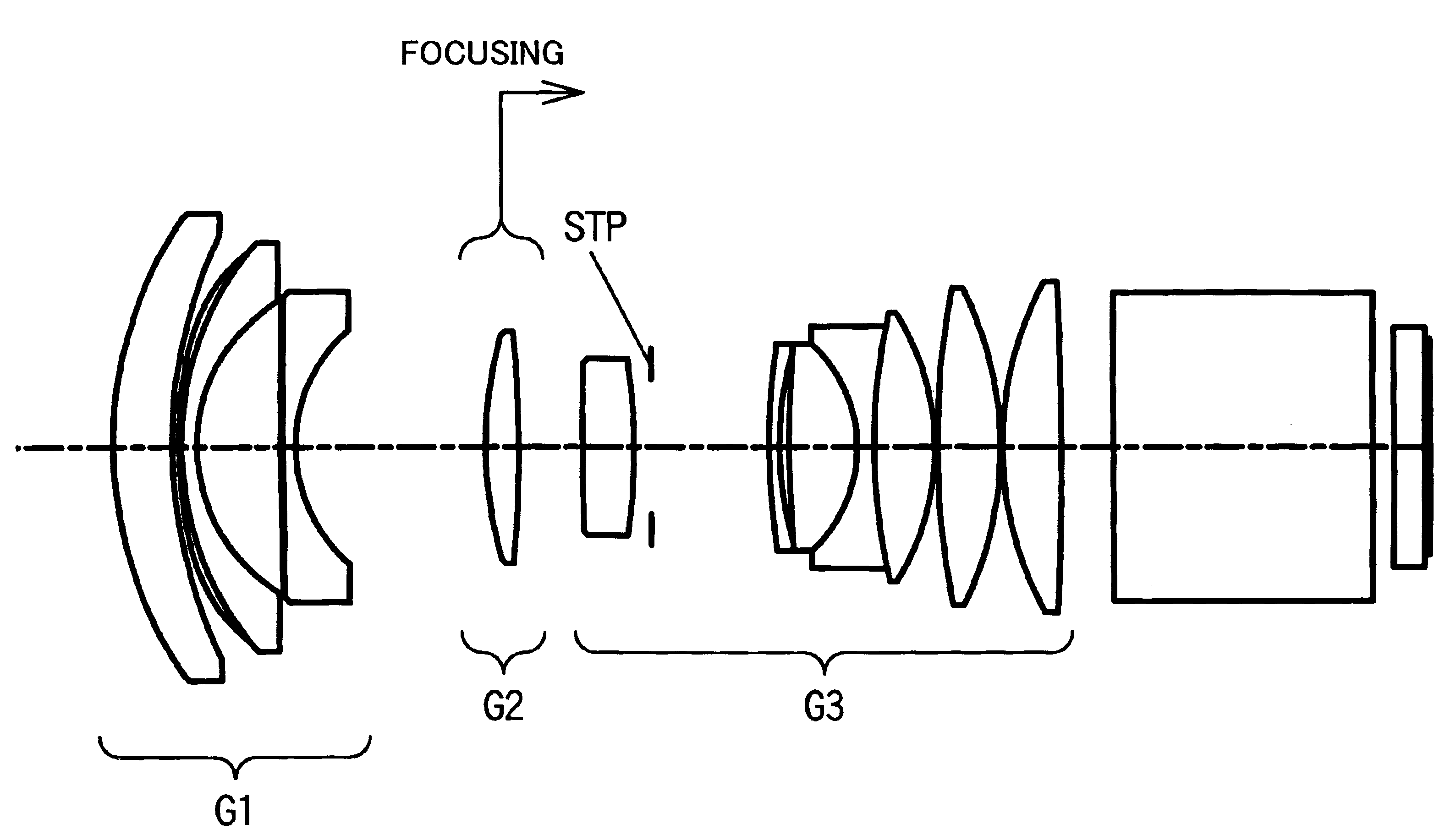
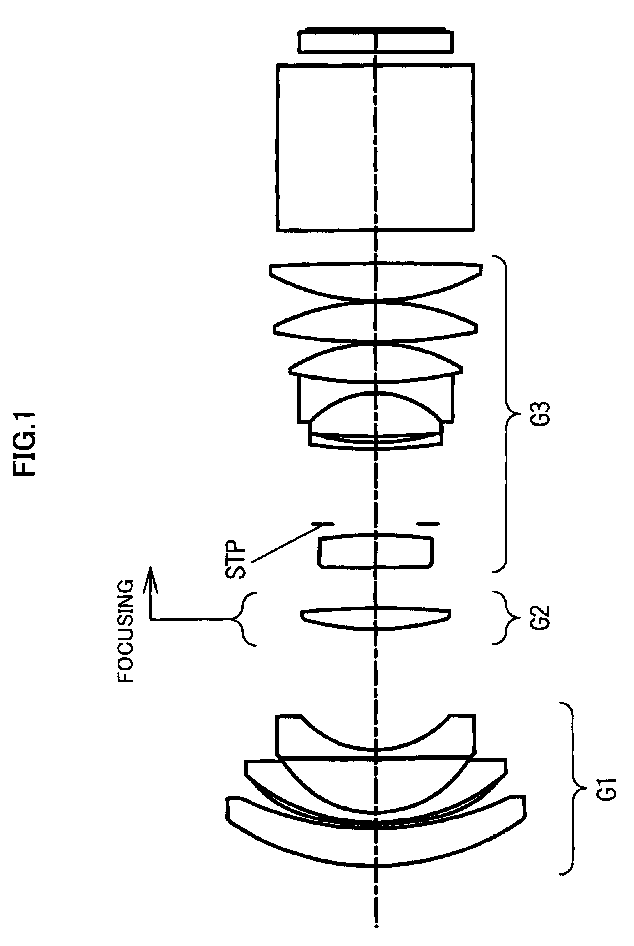
[0023]FIG. 1 is a cross sectional view of lenses in the exemplary projection lens system. In FIG. 1, reference alphanumerical symbols G1, G2 and G3 denote a first group of lenses of negative refractive power, a second group of lenses of positive refractive power, and a third group of lenses of positive refractive power, respectively, and STP designates an aperture stop.

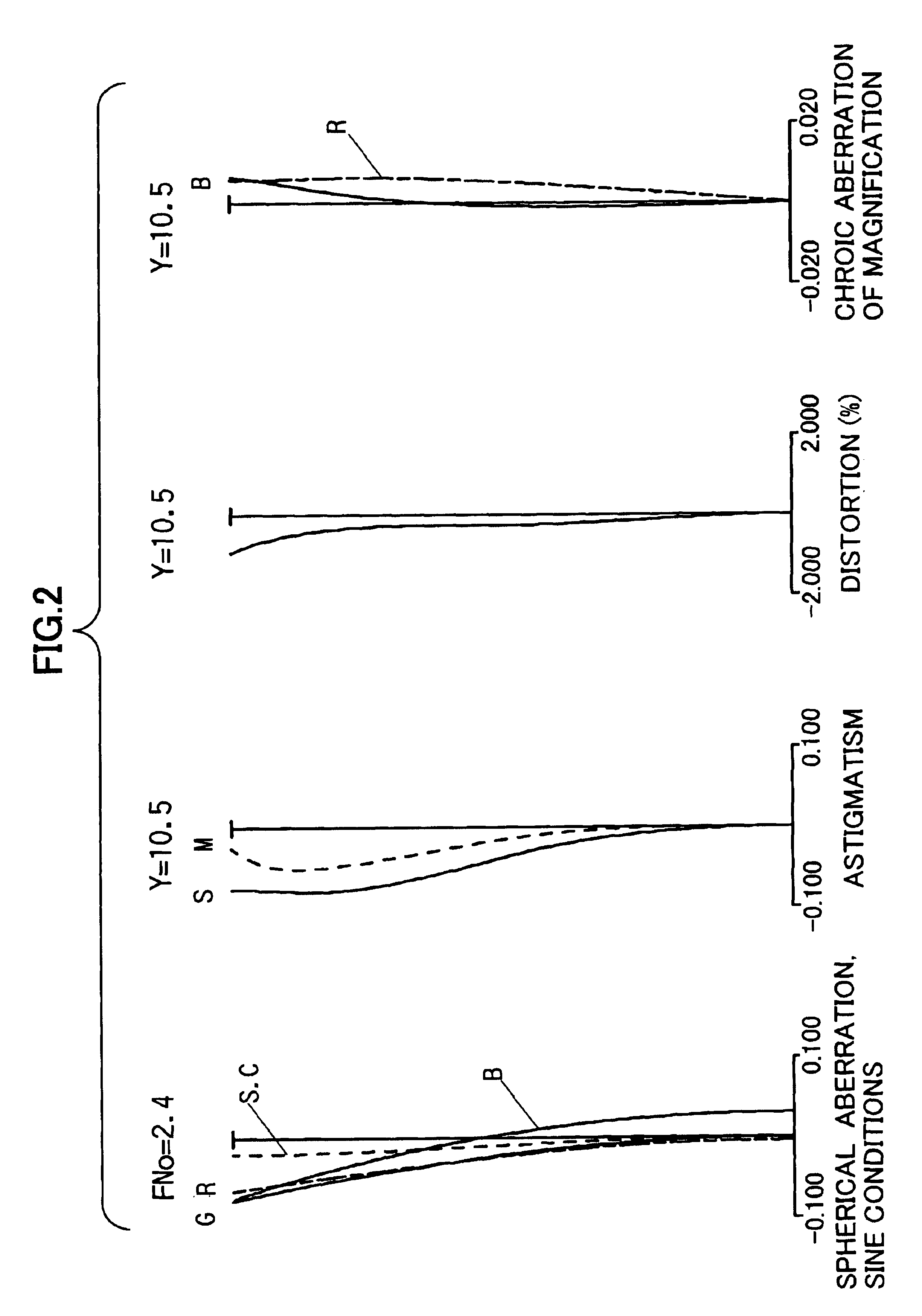
[0024]FIGS. 2, 3 and 4 are diagrams illustrating aberrations in 40-inch, 52-inch and 61-inch dimensions of screen occurred in the exemplary projection lens system, respectively. In FIGS. 2 and 4, aberrations for wavelengths λ=450 nm, =546 nm, and =650 nm are denoted by B for Blue, G for Green and R for Red, respectively.

[0025]In the exemplary projection lens system, f is a focal length, F no is an F number, # is a plane number, r is a radius of curvature of a lens plan...


PUM


Abstract

A compact and light-weighted projection lens system that is capable of projecting an image at an angle as wide as 75 degrees with sufficient field angle and brightness as represented by F number of approximately 2.4, that is capable of effectively correcting chroic aberration of magnification and aberration of distortion and exhibiting optical stability against environmental variations, and that is suitable for obtaining an extraordinarily fine image by the magnification and projection. In the projection lens system that comprises first to third groups of lenses in the order from the closest a magnified image where the first lens group of negative refractive power includes one or more aspherical lenses each having an aspherical plane on one or both of the surfaces, the second lens group of positive refractive power includes one or more positive lenses, and third lens group of positive refractive power includes one or more cemented triplet lenses comprised of three lenses of positive, negative, and positive attributes joined in this order, a projection lens system is characterized by terms and conditions defined as in the following formulae:0.9<|f1| / f<1.4  (1)2.1<f2 / f<3.4  (2)1.9<f3 / f<2.8  (3)where f is a total focal length throughout the projecting lens system, f1 is a focal length of the first group of lenses, f2 is a focal length of the second group of lenses, and f3 is a focal length of the third group of lenses.

Description

FIELD OF THE INVENTION[0001]The present invention relates to a projection lens system dedicated to magnifying and projecting an image presented by a liquid crystal display device, a digital micro mirror device, or the like, and more particularly, it relates to a projection lens system of which projection field angle is about 75 degrees, F number is about 2.4, and reducing optics are generally telecentric.PRIOR ART[0002]Conventionally, there have been proposed a variety of projection lens systems used to magnify and project an image from an apparatus like a liquid crystal display device onto a screen. For these recent years, more downsized image projection display apparatuses have been continually developed, and miniaturization of a projection lens system and maximization of its field angle are requirements for downsizing. Especially, a projection lens system of widened field angle often employs the so-called “negative lens leading optical system” where among several lens groups, the...

Claims


Application Information

Patent Timeline
IPC IPC(8): G02B13/18G02B9/12G02B13/24G02B13/04
CPCG02B13/04G02B13/22
Inventor YAMADA, YASUHARU
Owner TAMRON
Why Eureka
Try Eureka