
Land grid array socket

a technology of land grid array and socket, which is applied in the direction of coupling device connection, electrical apparatus construction details, engagement/disengagement of coupling parts, etc., can solve the problems of large contact pressure to be exerted on the socket, socket lacks sufficient strength for use with lga packages, and requires a larger footprint on the printed circuit board than the actual occupied space of the socket itself, so as to prevent deformation of the socket housing and reduce the effect of bending

Inactive Publication Date: 2006-02-21
TYCO ELECTRONICS JAPAN GK
View PDF12 Cites 122 Cited by
  • Summary
  • Abstract
  • Description
  • Claims
  • Application Information

AI Technical Summary

Benefits of technology

[0007]It is, therefore, an object of the invention to provide a LGA socket that has sufficient strength so that deformation of a housing of the socket is prevented when the socket is fitted to a LGA package wherein the socket has a simple construction for ease of installation. It is another object of the invention is to provide a LGA socket in which sufficient strength is ensured without increasing the size of a footprint of the socket. It is still another object of the invention to provide a durable LGA socket.

Problems solved by technology

The mating of the contacts in the IC package with the corresponding contacts in the socket typically causes a large contact pressure to be exerted on the socket.
Although this socket is suitable for use with PGA packages, this socket lacks sufficient strength for use with LGA packages wherein the LGA package is pressed from above the socket and a large vertical force is exerted on the socket in a direction substantially perpendicular to a printed circuit board.
This configuration, however, requires a larger footprint on the printed circuit board than that actually occupied by the socket itself.
Thus, the socket size is large, a large number of parts, such as, screws, are required, and assembly is complicated.
In this configuration, however, the printed circuit board is susceptible to warping.
Since the protrusion or the elastic interlocking element is made of resin, the protrusion or the elastic interlocking element is apt to wear-out due to friction with the lever during operation of the lever.
The socket, therefore, is not durable.
Forming the protrusion or the interlocking element as a separate metal member, however, increases the number of parts and the manufacturing costs.
Further, if the housing of the socket deforms when the LGA package is pressed by a cover member to form electrical connections between the contacts, the electrical contact array may become warped and deteriorate the electrical connections between the contacts.
A force applied to the lever for actuation will also not efficiently be transferred, because the force will be absorbed by the deformation of the housing.

Method used


Image

  • Land grid array socket
  • Land grid array socket
  • Land grid array socket

Examples


first embodiment

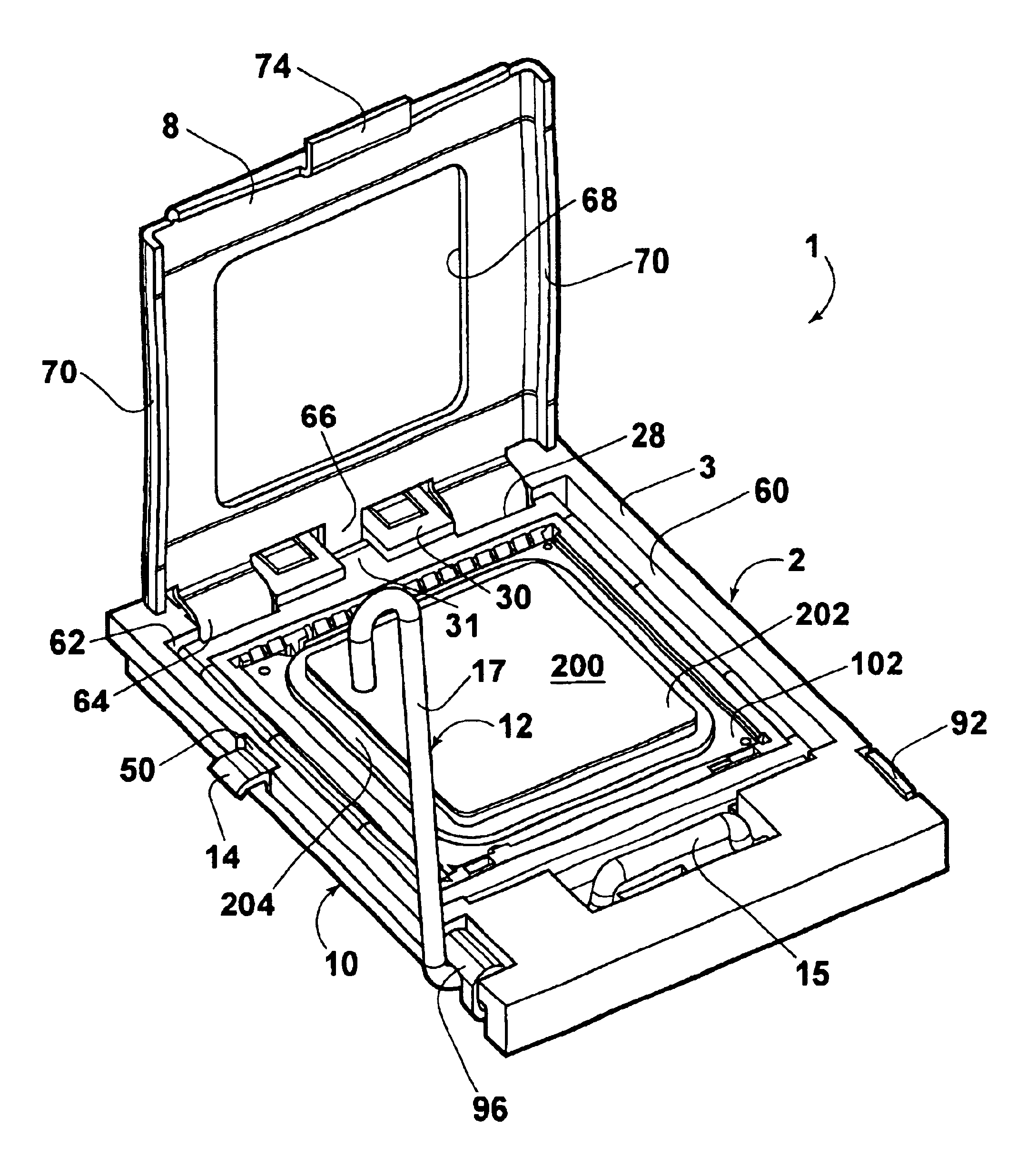
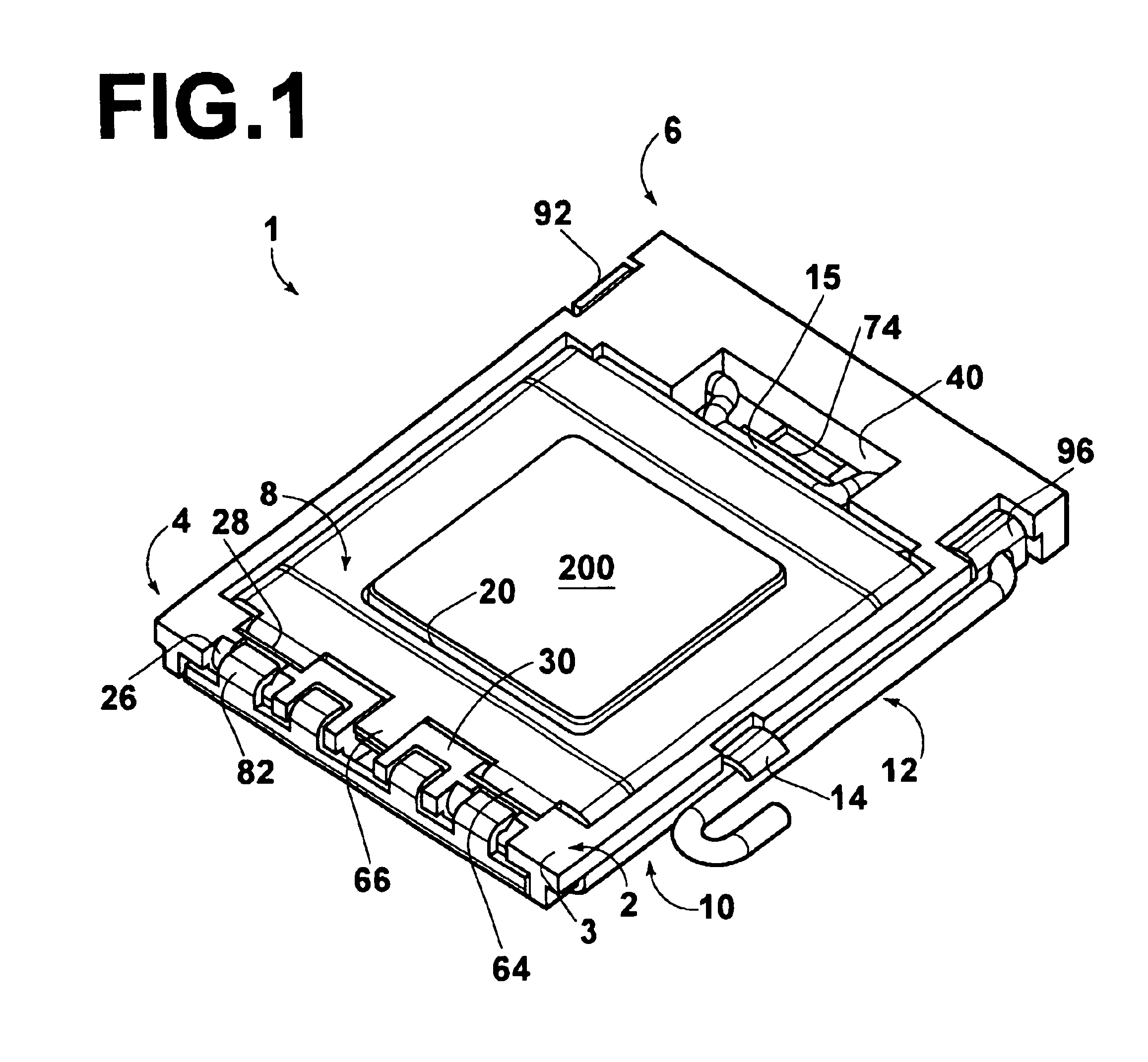
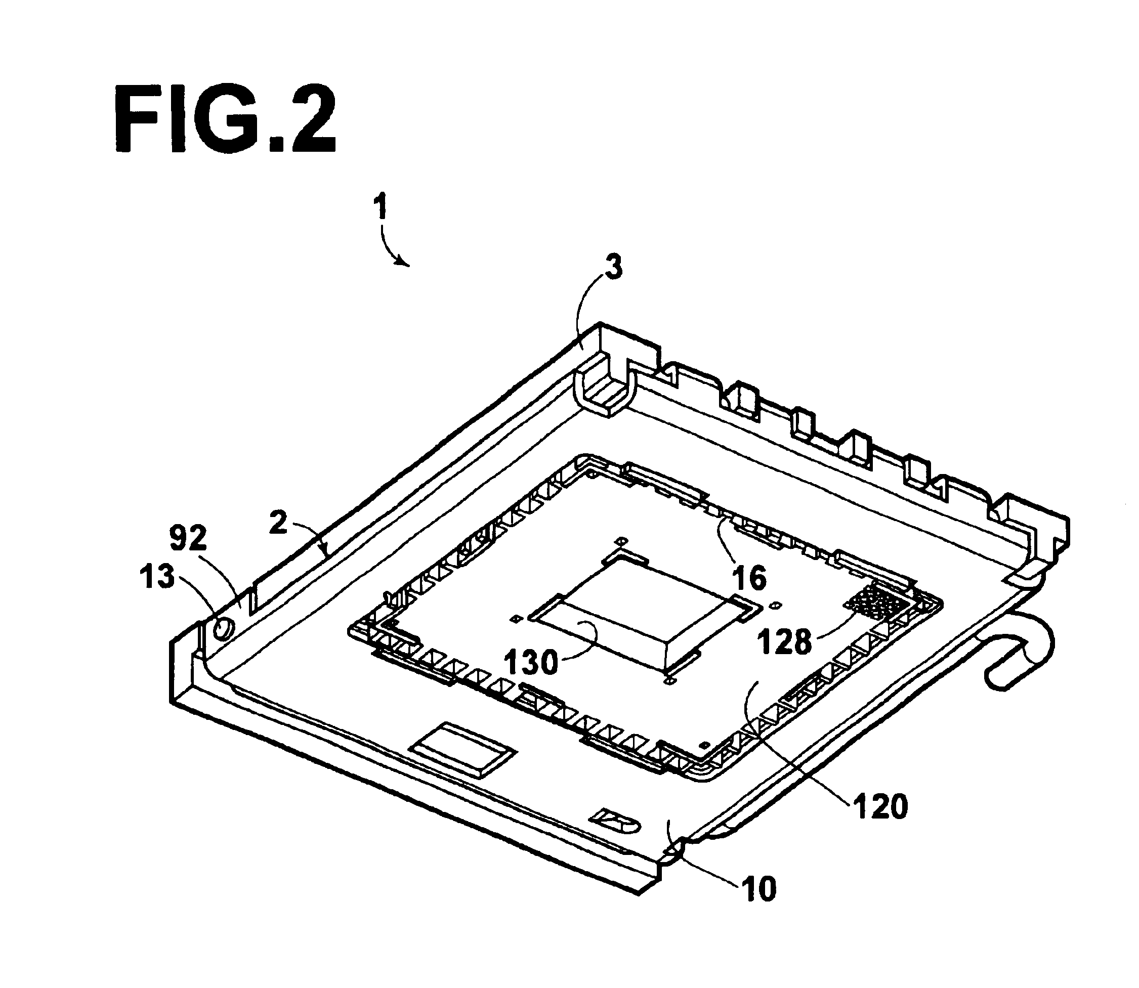
[0036]FIG. 1 shows a land grid array (LGA) socket 1 (hereinafter, simply referred to as “socket”) according to the invention with a LGA package 200 fitted therein. As shown in FIGS. 1 and 2, the socket 1 includes an insulative housing 2 molded from resin or the like (hereinafter, simply referred to as “housing”). The housing 2 has a rectangular frame body comprising an outer housing 3 and an inner housing 120. A cover member 8 is pivotally mounted on a first end 4 of the housing 2. The cover member 8 has a rectangular opening 68 (FIG. 6A). As shown in FIG. 2, a metallic reinforcing plate (hereinafter, simply referred to as “reinforcing plate”) 10 is attached to a bottom surface 11 (FIG. 3B) of the housing 2. A lever 12 is pivotally supported on a second end 6 of the housing 2. The lever 12 engages with a free end of the cover member 8 to lock the cover member 8 to the housing 2.

[0037]The individual elements of the socket 1 will now be described in greater detail. As shown in FIG. 3,...

second embodiment

[0057]Because the housing 302 is supported by the reinforcing plate 310 on the two sides extending between the first end 304 and the second end 306, deformation of the housing 302 is prevented when a force is exerted on the housing 302 during connection of the LGA package 200. Additionally, the second embodiment has a decreased weight because the metallic reinforcing plate 310 does not extend entirely about the circumference of the bottom of the housing 302. Because the cover member 8 is configured to be pivotally supported by the reinforcing plate 310 on the first end 304 of the housing 302, excessive load is not imposed to even the first end 304 of the housing 302 so that deformation of the housing 302 may be prevented. Further, because both the cover member 8 and the reinforcing plate 310 have apertures for the shaft 326, and the cover member 8 is constituted by a metallic shaft member separated from the reinforcing plate 310 and pivotally supported by the reinforcing plate 310, ...


PUM


Abstract

A land grid array socket comprises an insulative housing having a plurality of contacts. The insulative housing has a top surface for receiving a land grid array package. A cover member is pivotally mounted on a first end of the insulative housing. The cover member is pivotal between an open position and a closed position where the cover member presses the land grid array package toward the top surface of the insulative housing so that the land grid array package electrically connects to the contacts. A lever is pivotally mounted on a second end of the insulative housing. The lever has a locking portion for locking the cover member in the closed position. A metallic reinforcing plate is positioned on a bottom surface of the housing. The metallic reinforcing plate extends between the first end and the second end of the insulative housing.

Description

FIELD OF THE INVENTION[0001]The invention relates to a land grid array (LGA) socket having an insulative housing with contacts that are electrically connected under pressure with corresponding contacts in a LGA package accommodated in the insulative housing to form an electrical connection between the LGA package and a printed circuit board.BACKGROUND OF THE INVENTION[0002]Various types of conventional integrated circuit (IC) sockets for attaching IC packages are known. Each of the IC packages has a large number of contacts that are arranged in a matrix-like array. The IC packages are classified as pin grid array (PGA) packages, ball grid array (BGA) packages, or land grid array (LGA) packages depending on the shape of an electric contact portion of the contacts. The contacts in each of the IC packages are brought into contact with corresponding contacts arranged in a housing of the socket to establish electrical connections therebetween. The mating of the contacts in the IC package...

Claims


Application Information

Patent Timeline
IPC IPC(8): H01R13/62H01R33/76H01L23/32H01L23/40H05K7/10
CPCH01L23/32H01L23/4093H05K7/1084H01L2924/0002H01L2924/00
Inventor SHIRAI, HIROSHIINOUE, MASASHIHASHIMOTO, SHINICHI
Owner TYCO ELECTRONICS JAPAN GK
Learn More