Antenna assembly with injection-molded seal

Inactive Publication Date: 2006-02-14
HIRSCHMANN ELECTRONICS GMBH & CO KG
View PDF11 Cites 16 Cited by
  • Summary
  • Abstract
  • Description
  • Claims
  • Application Information

AI Technical Summary

Benefits of technology

[0006]It is therefore the principal object of the present invention to provide an improved antenna assembl

Problems solved by technology

This prior system has a drawback in that water or moisture can penetrate through the opening into the interior of the vehicle body and the penetration of moisture can affect any electronic elements which are provided beneath the assembly.
The penetration of moisture or liquid water can adversely affect electronic components to the point that signals cannot be received by the antenna.
The problem c

Method used


Image

  • Antenna assembly with injection-molded seal
  • Antenna assembly with injection-molded seal
  • Antenna assembly with injection-molded seal

Examples


Example

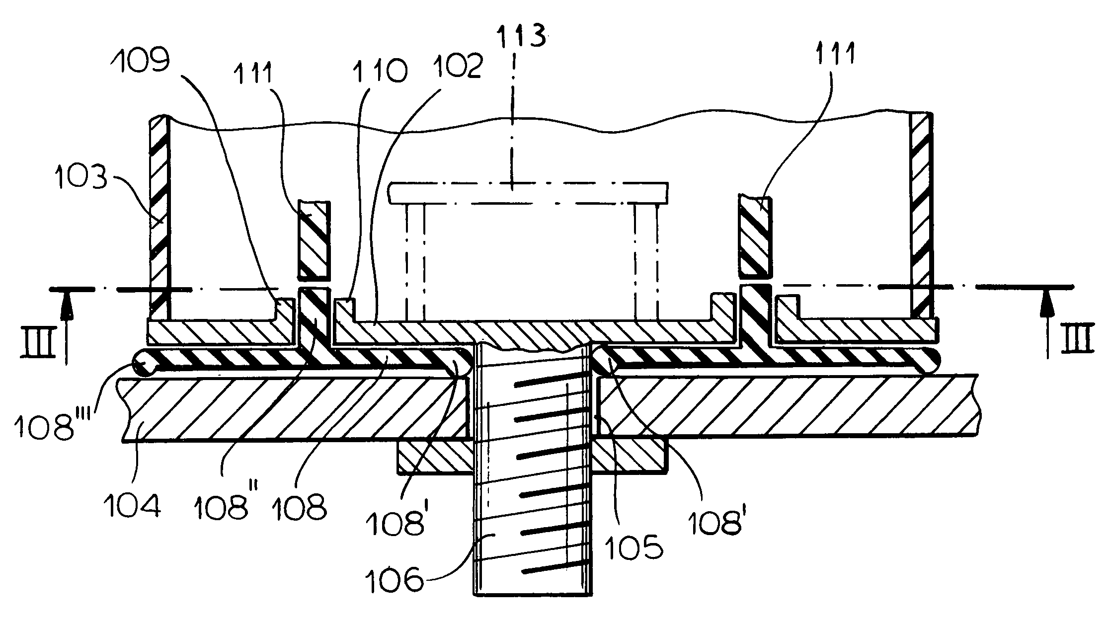
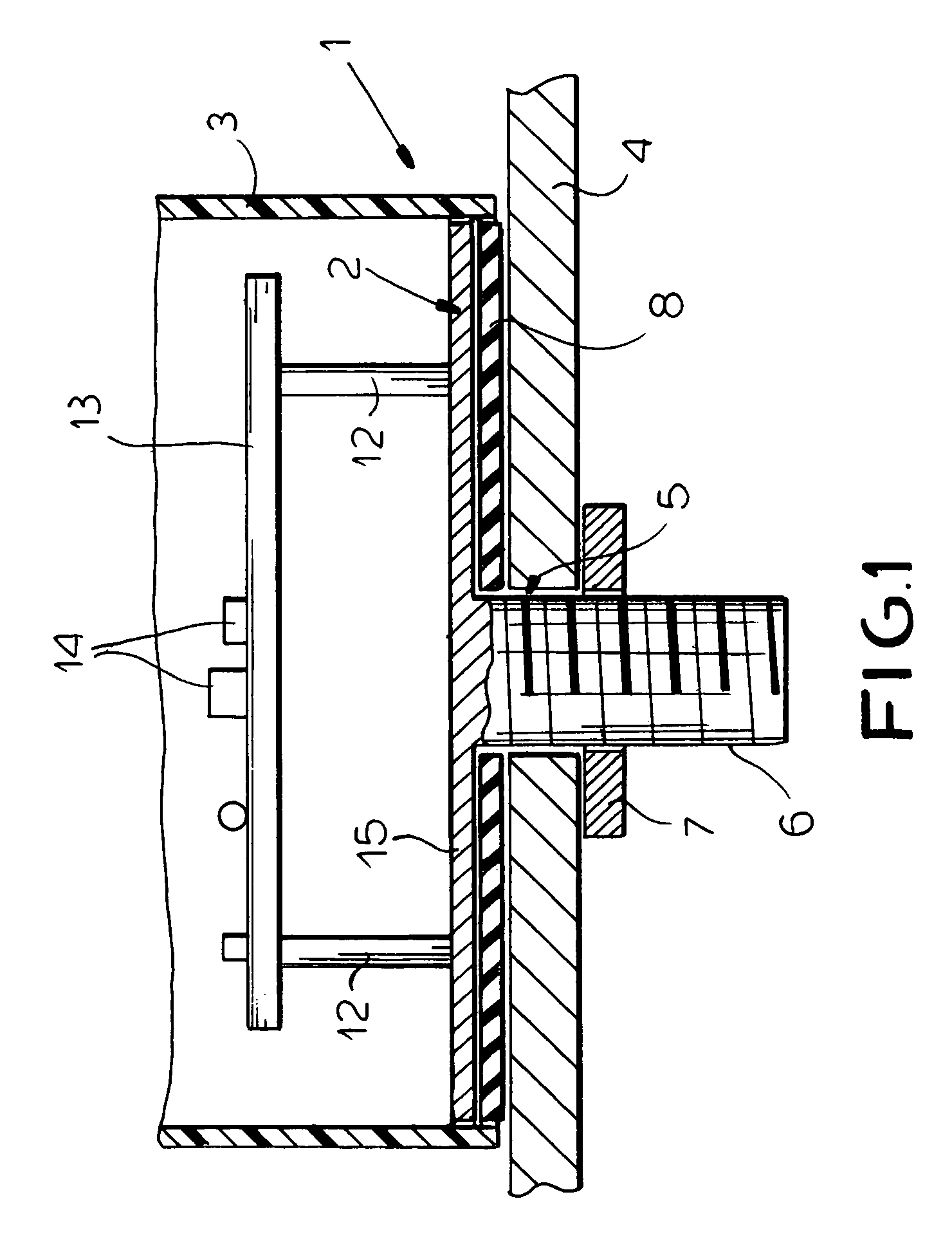
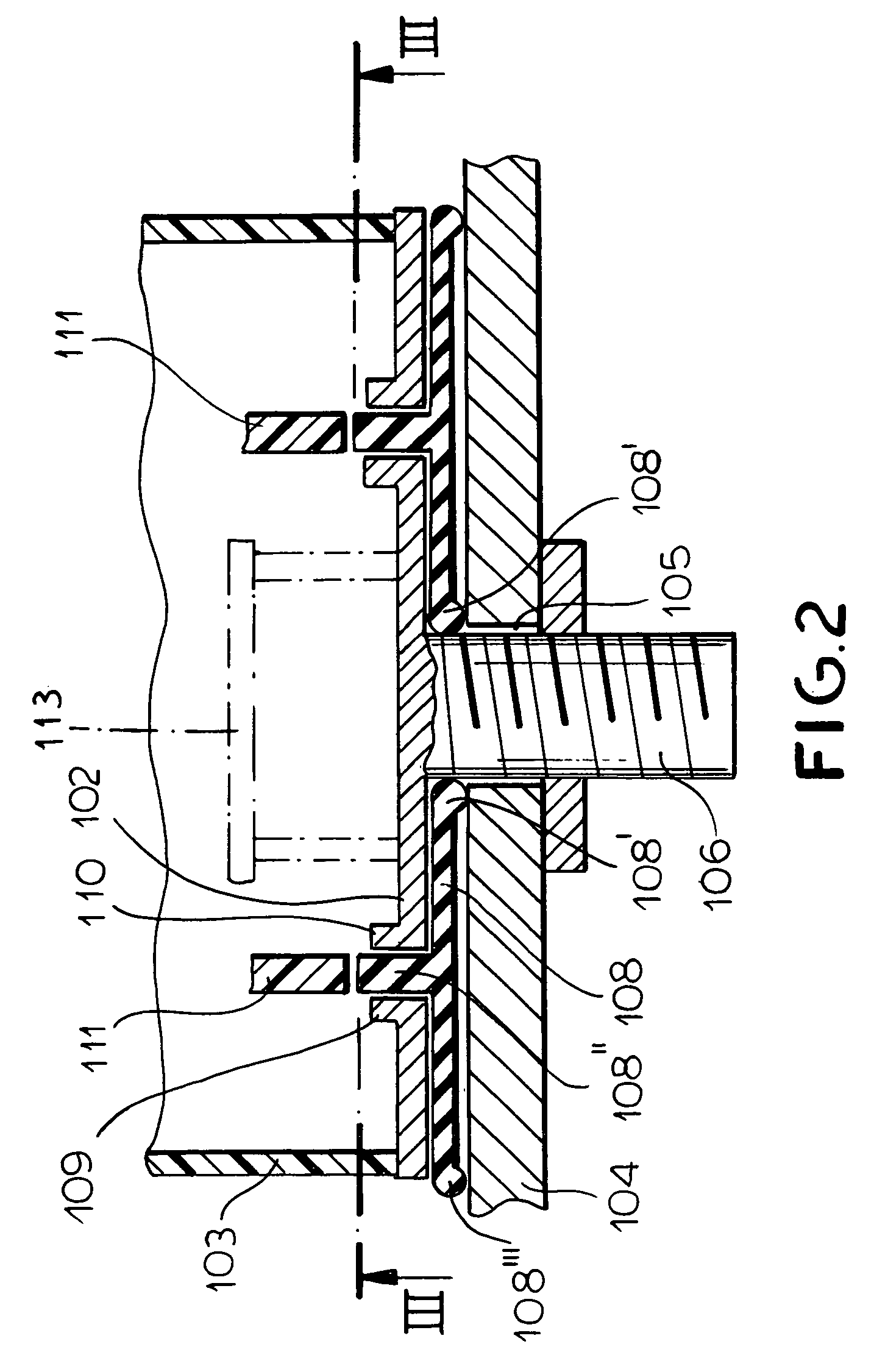
[0018]The antenna 1 shown in FIG. 1 comprises a base body 2 which is comprised of metal. The base body 2 is produced by a die casting process or is formed as a stamped or punched out metal piece. Upon the base body 2 a housing 3 of a synthetic resin material is seated. The housing 3 surrounds the antenna elements optionally including electronic components such as an amplifier when the same are provided and protects them. The antenna elements will themselves vary depending upon the purpose and applications of the antenna 1. The antenna components have been shown diagrammatically at 14 and can be carried by a printed circuit board 13 mounted on posts 12 on the plate-shaped portion 15 of the base body 2 (FIG. 1).

[0019]The vehicle body wall 4 has an opening 5 which can be referred to as the vehicle body opening, in which a projection 6 with a screw thread engages. The projection 6 can be formed as an extension of the base body 2. To retain or fix the antenna 1 on the vehicle body wall 4...


PUM


Abstract

An antenna assembly for mounting an antenna on a vehicle body, especially upon the roof of a vehicle, in which the assembly has a base body of metal with a threaded projection passing through a hole in a wall of the vehicle body. A housing of plastic encloses the antenna components mounted upon a plate-shaped portion of the base body and a seal is provided between the base body and the vehicle body and seals around the opening between the base body and the wall of the vehicle. The seal can be injection molded and molded onto the base body in the injection-molding process.

Description

FIELD OF THE INVENTION[0001]Our present invention relates to an antenna assembly, especially for mounting on an automotive vehicle body and particularly on a roof of an automotive vehicle, with a seal preventing the penetration of moisture, water and contaminants into the interior of the vehicle, especially an injection-molded seal.BACKGROUND OF THE INVENTION[0002]An antenna for a motor vehicle is described in the German patent document DE 295 00 961 E1. This antenna has a base plate or base body composed of metal and which carries antenna elements, for example a strip-conductor antenna. To protect the antenna elements which can be mounted on that base plate, an antenna housing, which can be composed of a nonconductive material like, for example, a synthetic resin material, is provided on the base plate to enclose those elements.[0003]The base plate can be a threaded pin which can be inserted into a hole in the vehicle body and which can enable the antenna assembly to be affixed on ...

Claims


Application Information

Patent Timeline
IPC IPC(8): H01Q1/32H01Q1/12
CPCH01Q1/3275H01Q1/1214
Inventor KORDASS, JOACHIMBLICKLE, GUNTHERWISCHNIOWSKI, BORIS
Owner HIRSCHMANN ELECTRONICS GMBH & CO KG
Why Eureka
Try Eureka