
Method of repairing tubular members on oil and gas wells

a tubular member and oil well technology, applied in mechanical equipment, sealing/packing, borehole/well accessories, etc., can solve the problems of structural weakening or perforation of corrosion cells, prior art fails to address the problem of structural reinforcement for structural members that have become weak, and prior art systems do not address concentric, pipe within pipe configurations

Inactive Publication Date: 2006-02-14
MADCON CORP
View PDF35 Cites 53 Cited by
  • Summary
  • Abstract
  • Description
  • Claims
  • Application Information

AI Technical Summary

Benefits of technology

"The present invention provides a method for repairing an oil or gas well with a platform that has an outer drive pipe, inner production flow line, and one or more intermediate conductors or surface casing strings that are concentrically positioned in between the inner production flow line and the outer drive pipe. The method identifies a corrosed or damaged portion of the intermediate conductor or casing and installs a repair member (e.g. half sleeve, quarter sleeve, curved plate) that spans between upper and lower positions that are above and below the damaged section. The repair member can be metallic or non-metallic (e.g. composite). The method also involves removing a section of the drive pipe and adding a grout product to the annulus between the outer drive pipe and inner conductor or casing string. The repair method restores structural integrity and pressure containment / load capacity for the casing or conductor that is repaired and thus to the casing string assembly below the casing head assembly."

Problems solved by technology

This creates a corrosion cell that can structurally weaken or perforate the conductor or surface casing.
However, the prior art fails to address a problem of structural reinforcement for structural members that have become weak because of the corrosive and / or mechanical effects of the surrounding environment.
Further, these patented prior art systems do not address concentric, pipe within pipe configurations.

Method used


Image

  • Method of repairing tubular members on oil and gas wells
  • Method of repairing tubular members on oil and gas wells
  • Method of repairing tubular members on oil and gas wells

Examples


Embodiment Construction

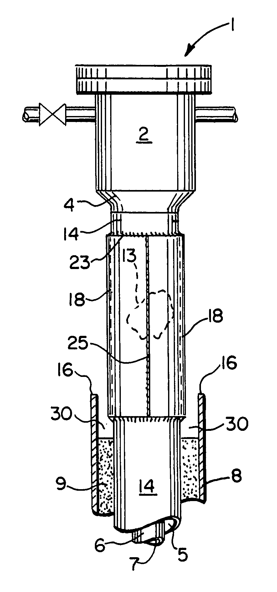
[0041]FIGS. 1–4 show the preferred method and apparatus of the present invention. A second embodiment of the method and apparatus of the present invention is shown in FIGS. 5 and 6. A third embodiment of the method and apparatus of the present invention is shown in FIGS. 7–10.

[0042]A fourth embodiment of the method and apparatus of the present invention is shown in FIG. 11. A fifth embodiment of the method and apparatus of the present invention is shown in FIG. 12.

[0043]FIGS. 13–15 show a sixth embodiment of the method and apparatus of the present invention.

[0044]In FIG. 1, a wellhead area 1 is shown that has a casing head assembly 2 of a gas or oil well. Connected to the casing head assembly 2 is a casing string 3. Flanges at the top of the casing head assembly 1 can accept either a blow out preventor (BOP) for drilling operations, or a wellhead / “christmas tree” for production. Inside the casing string 3 there is provided a casing string bore 5 that contains a production tubing or ...


PUM


Abstract

The disclosure concerns a method and apparatus for repairing or structurally reinforcing an oil and gas well tubular member, or an assembly of tubular members. The assembly to be repaired can include a smaller diameter inner flow conveying conduit (or production tubing) and a larger diameter concentrically placed surface casing, providing an annulus in between the production tubing and the surface casing. A third casing pipe of largest diameter, the drive pipe is placed around the surface casing string. Other “conductor” casing pipes can be positioned around the surface casing inside the drive pipe. Part of the surface casing string (or other conductor pipe) can suffer damage due to corrosion. A sleeve or repair member is placed around the casing string or other tubular member at a damaged portion.

Description

CROSS-REFERENCE TO RELATED APPLICATIONS[0001]Not applicableSTATEMENT REGARDING FEDERALLY SPONSORED RESEARCH OR DEVELOPMENT[0002]Not applicableREFERENCE TO A “MICROFICHE APPENDIX”[0003]Not applicableBACKGROUND OF THE INVENTION[0004]1. Field of the Invention[0005]The present invention relates to a new method and apparatus that does not mandate the use of a drilling rig for repairing and structurally reinforcing tubular members that are next to a casing head assembly on an oil or gas well, and in one embodiment, casing string (or other conductors) contained inside of an outer drive pipe.[0006]2. General Background of the Invention[0007]In the oil and gas well drilling and production industry, casing arrangements are typically used as part of a well. These casing arrangements often include a smaller diameter inside production casing contained concentrically within the bore of a larger diameter surface casing string. There may be additional casing strings referred to as conductors. The o...

Claims


Application Information

Patent Timeline
Patent Type & Authority Patents(United States)
IPC IPC(8): E21B29/10F16L55/17
CPCE21B29/10F16L55/17F16L55/1683F16L55/175
Inventor TRADER, BRUCEHOFMEISTER, GEORGE
Owner MADCON CORP
Learn More