
Junk mail rejection system

a rejection system and mail technology, applied in the field of junk mail rejection system, can solve the problems of affecting the system, affecting the service life of subscribers, and affecting the quality of electronic mail, and achieve the effect of effectively preventing junk mail

Inactive Publication Date: 2006-02-07
NIHON DIGITAL
View PDF14 Cites 43 Cited by
  • Summary
  • Abstract
  • Description
  • Claims
  • Application Information

AI Technical Summary

Benefits of technology

[0009]In view of the foregoing and other drawbacks, disadvantages and problems of the conventional methods and structures, the first object of the present invention is to provide a junk mail rejection system capable of effectively preventing junk mail.
[0010]The second object of the present invention is to provide a junk mail rejection system capable of preventing the damage by junk mail transmitted with a view to acts of terrorism.

Problems solved by technology

On the other hand, with an increasing utilization factor of electronic mail, there arises the social problem that the amount of electronic mail from an undesired source, that is, junk mail, has largely increased.
Especially when the service fee is charged to a receiving subscriber depending on the amount of information received by the subscriber from the center in the system of the Internet service, the total amount of payment of the subscriber who receives junk mail increases due to the junk mail, thereby causing the subscriber to suffer a loss.
However, it means to largely change an entire system, and requires a high cost.
However, this method cannot completely avoid a loss by junk mail having a large amount of information.
Furthermore, there can also be a method of changing the electronic mail address of a subscriber, but changing an electronic mail address requires notifying all possible transmitters of desired electronic mail of the change of the electronic mail address, thereby imposing a heavy load on the subscriber.
However, the ‘specified reception’ is restricted in the number of electronic mail addresses to be specified, and electronic mail to be received cannot be received if it is not specified.
Similarly, since reception of all electronic mail is rejected in the ‘batch rejection’, electronic mail to be received cannot be received.
Additionally, since a source electronic mail address of junk mail can be constantly changed, the junk mail cannot be effectively avoided in the ‘specified rejection’.
Another problem with the junk mail is that old necessary electronic mail is removed by a large amount of junk mail received when there is a restriction in the number of pieces of electronic mail to be stored for each subscriber and the predetermined number of pieces of later electronic mail is stored.
Furthermore, malicious electronic mail can be acts of terrorism of damaging the function of mail at the destination by intentionally concentrating a large amount of junk mail.
Additionally, it requires a cost of using a telephone line to delete a large amount of unnecessary mail, thereby badly damaging the subscriber.

Method used


Image

  • Junk mail rejection system
  • Junk mail rejection system
  • Junk mail rejection system

Examples


first embodiment

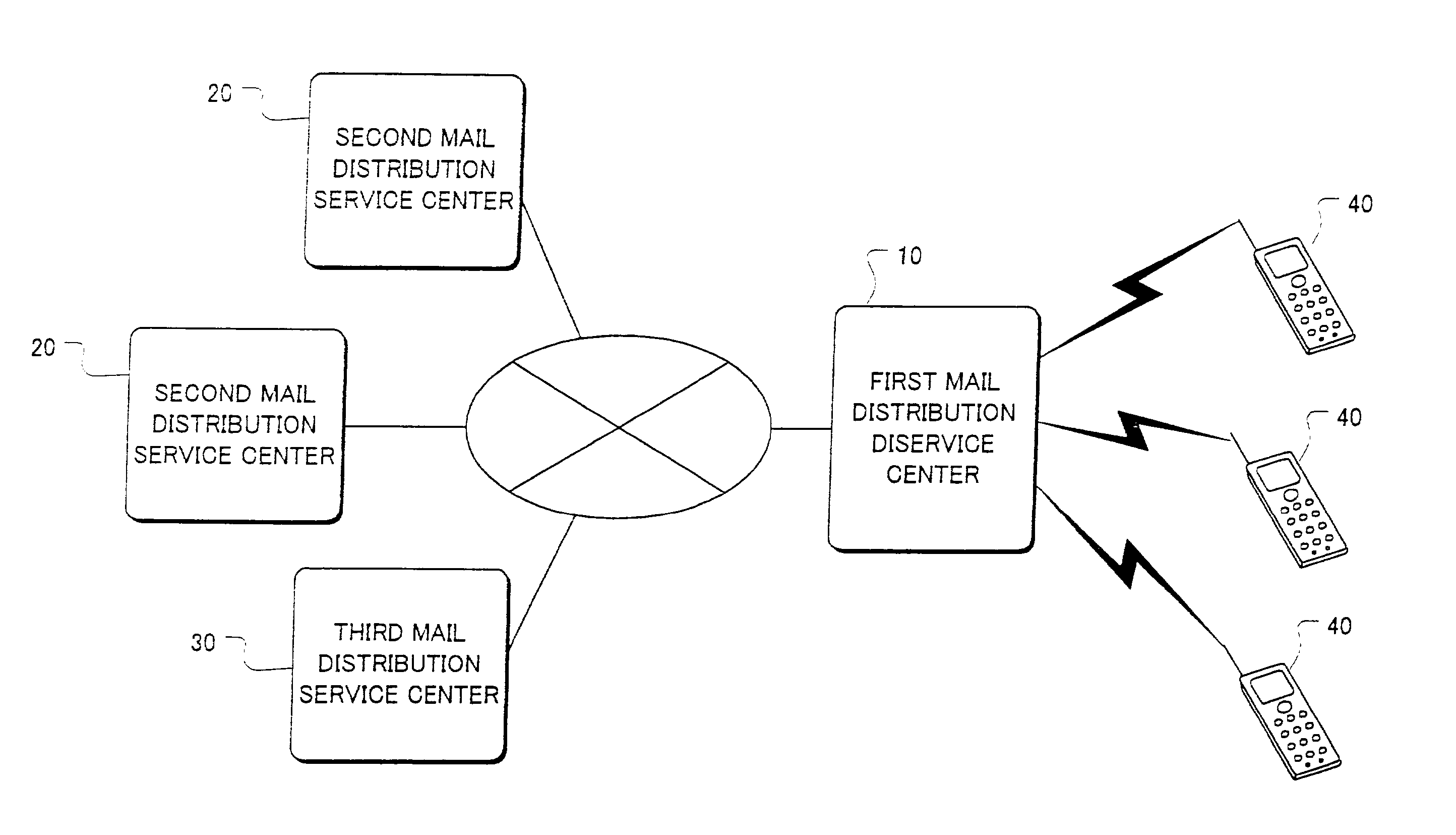
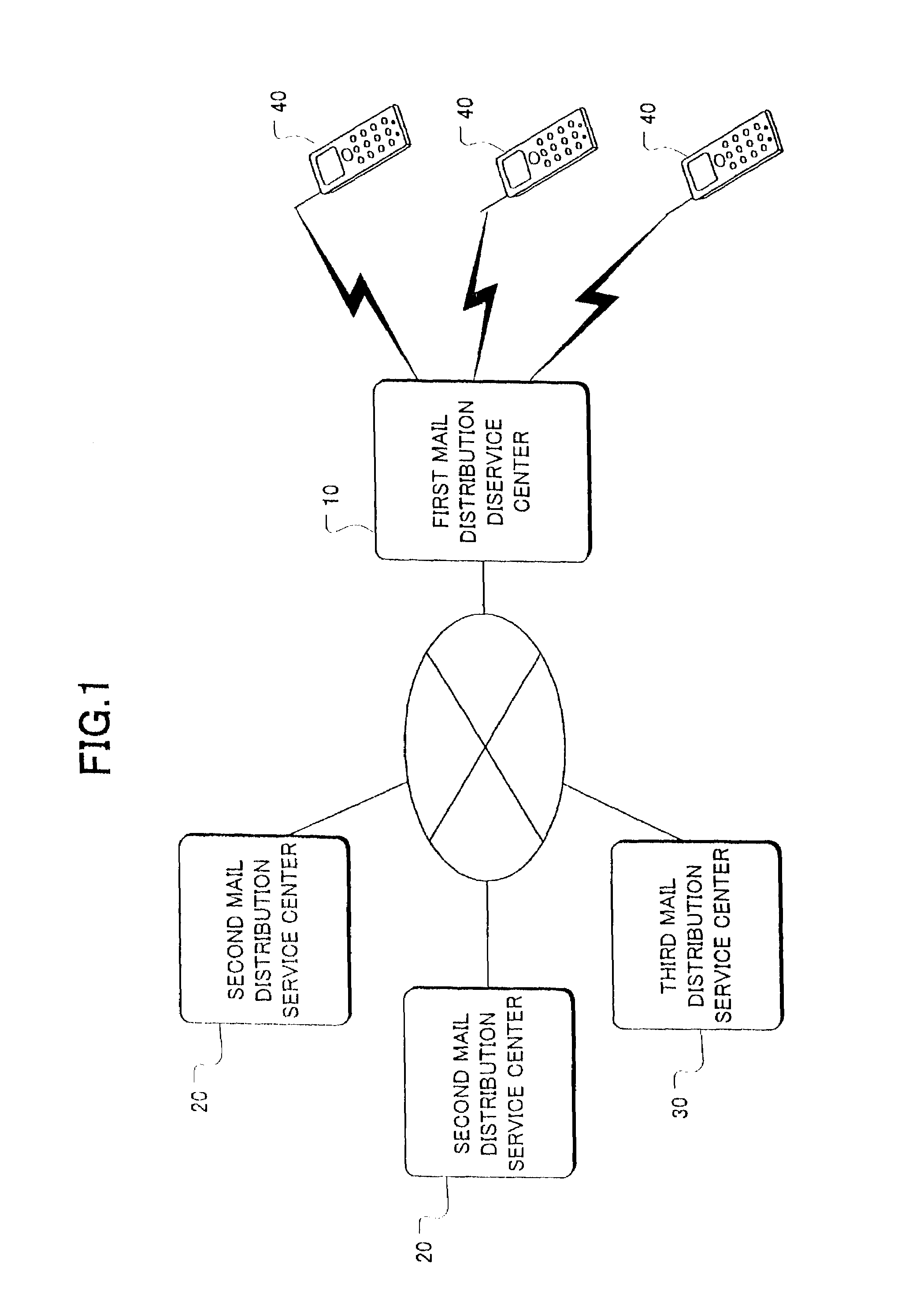
[0081]As described above, the risk of receiving junk mail can be shared among all first and second mail distribution service centers. Described below will be the system for protection against damage from concentrative and intentional transmission of a large amount of junk mail.

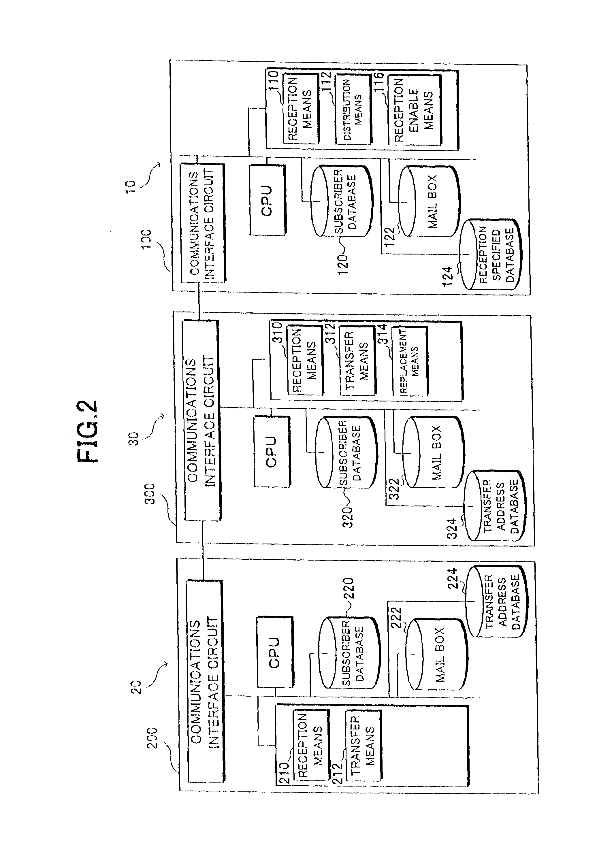
[0082]FIG. 8 is a block diagram of a configuration of a second embodiment of protection against terrorism. The configuration which is the same as or similar to that shown in FIG. 1 is assigned the same reference numeral, and the detailed explanation is omitted here. The second embodiment is different from the first embodiment in that it comprises a mail reception amount restriction means 316 and a setting means 318 as functions that the WWW server 300 performs by the program stored in the WWW server 300 of the third mail distribution service center 30. The WWW server 300 is provided with a reception amount restriction setting value database 326, and the reception amount restriction setting value database 326 ...

third embodiment

[0094]FIG. 11 is a block diagram of the configuration in which electronic mail can be received. A component which is the same as or similar to that shown in FIG. 1 is assigned the same reference numeral, and the detailed explanation thereof is omitted. This example is different from the above mentioned embodiments in that it comprises identification code assignment means 330 and direct electronic mail transmission means 334 as functions that the WWW server 300 performs by the program stored in the WWW server 300 of the third mail distribution service center 30. Furthermore, the WWW server 300 is provided with an identification code list database 340, and the subscriber database 320 stores an identification code DASP and a specified mail address associated with each subscriber.

[0095]The identification code DASP is a code indicating the attribute including the hobby, the liking, etc. of a subscriber and the attribute of a transmitter whose mail can be received by the subscriber in th...


PUM


Abstract

To provide a junk mail rejection system which can effectively reject junk mail in electronic mail. When junk mail transmitted from many and unspecified persons is sent to a first electronic mail address registered in a first mail distribution service center, sources of the junk mail are not acceptable electronic mail addresses, and a reception enable unit rejects receiving the junk mail, thereby avoiding transmission of the junk mail to subscribers. On the other hand, the electronic mail transmitted from many and unspecified persons and not to be rejected by the reception enable unit is transmitted to a second electronic mail address. The electronic mail to the second electronic mail address received by a second mail distribution service center is forwarded to a third mail distribution service center, and a replacement unit replaces a source with an acceptable electronic mail address registered in the first mail distribution service center, and the electronic mail is transmitted to the first mail distribution service center. Since the source is set to an acceptable electronic mail address, the reception enable unit in the first mail distribution service center enables reception, and a subscriber can receive the electronic mail.

Description

BACKGROUND OF THE INVENTION[0001]1. Field of the Invention[0002]The present invention relates to a junk mail rejection system for rejecting junk mail in electronic mail.[0003]2. Description of the Related Art[0004]Recently, as various networks such as Internet, etc. have been developed and wireless terminal equipment has made remarkable progress, more and more information has been transmitted and received by electronic mail, and a number of users utilize electronic mail personally and for business.[0005]On the other hand, with an increasing utilization factor of electronic mail, there arises the social problem that the amount of electronic mail from an undesired source, that is, junk mail, has largely increased. Now, an Internet service system using a wireless telephone as an example is explained. There is a center capable of gaining access through a network such as Internet, etc., and an electronic mail address is assigned to a wireless telephone of a subscriber. When electronic ma...

Claims


Application Information

Patent Timeline
IPC IPC(8): G06F13/00H04L12/58
CPCG06Q30/06
Inventor HASEGAWA, MASAKAZU
Owner NIHON DIGITAL
Learn More