
Igniter transformer

Inactive Publication Date: 2006-02-07
MURATA MFG CO LTD
View PDF7 Cites 17 Cited by
  • Summary
  • Abstract
  • Description
  • Claims
  • Application Information

AI Technical Summary

Benefits of technology

[0011]In order to overcome the problems described above, preferred embodiments of the present invention provide an igniter transformer wherein a secondary coil can be flattened without degrading the space factor, a uniform insulating coating can be coated on wires of the secondary coil, and the secondary coil and a primary coil are closely coupled so as to increase the inter-coil withstand voltage.
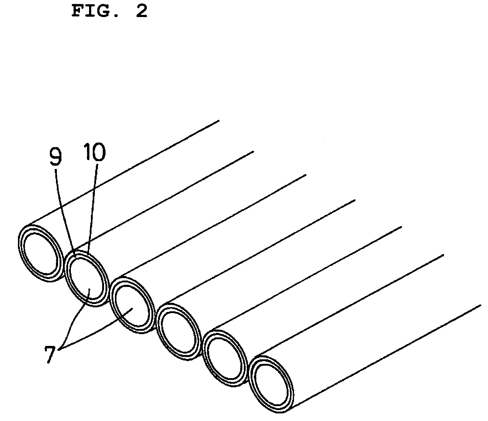
[0012]According to a preferred embodiment of the present invention, an igniter transformer includes a magnetic core, a secondary coil surrounding the magnetic core, a primary coil, and a plurality of round single-core wires, wherein the plurality of round single-core wires disposed substantially parallel to one another in a common plane are bonded side by side to form a flat multicore wire that is substantially rectangular in cross-section. The secondary coil is formed by the flat multicore wire which is edgewise wound such that the longer sides of the flat multicore wire face each other in the turns while standing upright. This structure eliminates excessive stress on each bent portion of the round single-core wires and the space factor of the secondary coil is not degraded even if the secondary coil including the edgewise-wound flat multicore wire is flattened. As a result, the thinner or lower-profile igniter transformer is advantageously provided.
[0013]Preferably, an igniter transformer includes the round single-core wire that has an insulating coating around the periphery of the round single-core wire and a fusible layer over the insulating coating, the flat multicore wire includes the plurality of round single-core wires consolidated by fusing the fusible layers of the round single-core wires, and the secondary coil includes a plurality of the flat multicore wires which are edgewise wound and the plurality of the flat multicore wires are bonded under pressure along the axis of the secondary coil such that the exposed fusible layers of the round single-core wires in the longer sides of the flat multicore wire are fused and the longer sides of the plurality of the flat multicore wires are bonded to each other. The secondary coil is defined by the flat multicore wire since the fusible layers of the round single-core wires are formed and the flat multicore wire is defined by fusing the fusible layers thereof. The round single-core wire advantageously allows formation of the insulating coating having a uniform thickness and the space factor of the secondary coil is increased.
[0014]Preferably, an igniter transformer includes the primary coil including a thin metal sheet that has a large width and that is wound substantially perpendicularly to the axis of the secondary coil. This structure allows the winding of the primary coil to be at the low-voltage side of the secondary coil with close coupling of the secondary coil and the primary coil. As a result, an inter-coil withstand voltage is advantageously increased.
[0015]Preferably, an igniter transformer includes the primary coil including a thin metal sheet that has a narrow width and that is wound substantially perpendicularly to the axis of the secondary coil, and the winding position of the primary coil shifts continuously in one direction along the axis of the secondary coil. Hence, the narrow thin metal sheet does not overlap in the turns. As a result, this structure advantageously provides close coupling of the secondary coil and the primary coil, and an inter-coil withstand voltage is increased.

Problems solved by technology

However, the flat wire forming the edgewise-wound secondary coil 22 has high tensile strength and is thus difficult to process.
Furthermore, a flat wire inherently causes eddy current loss, which may reduce the voltage generated by the igniter transformer.

Method used


Image

  • Igniter transformer
  • Igniter transformer
  • Igniter transformer

Examples


Embodiment Construction

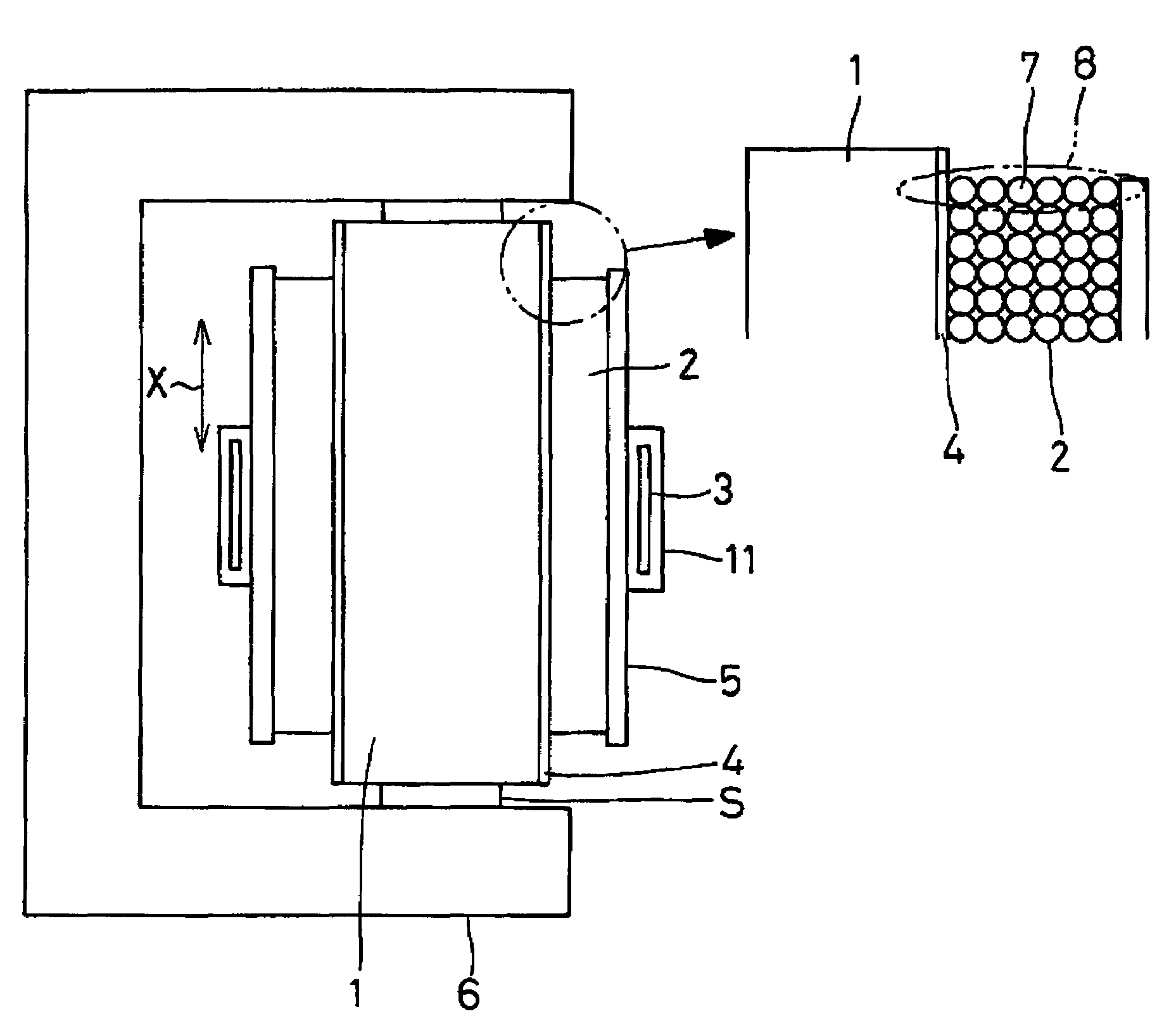
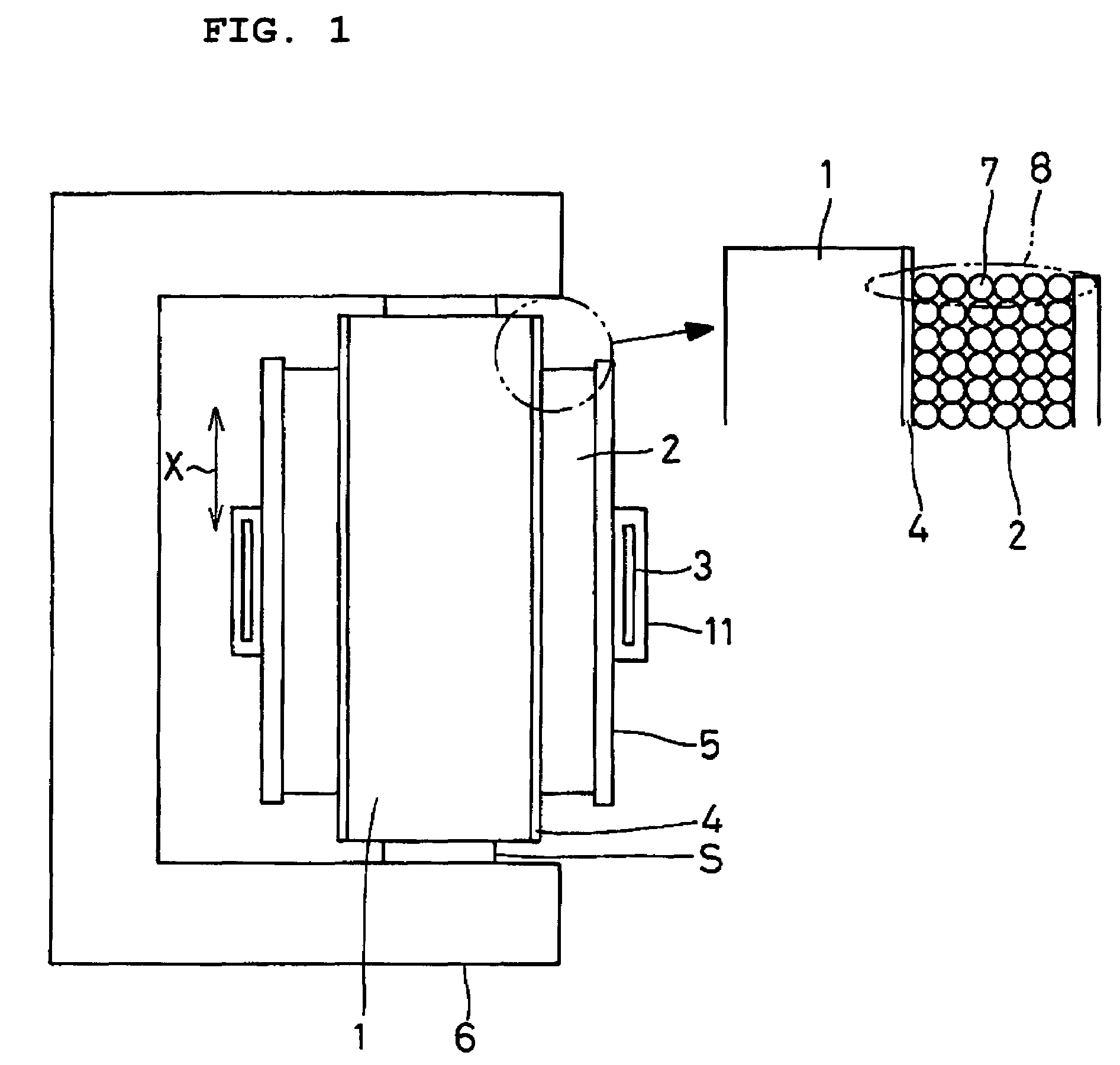
[0031]According to a preferred embodiment of the present invention, as schematically shown in FIG. 1, an igniter transformer includes a magnetic core 1 preferably having a substantially elliptic cross-section, a secondary coil 2 surrounding the magnetic core 1, and a primary coil 3 surrounding the secondary coil 2. An insulating film 4 is disposed between the outer surface of the magnetic core 1 and the inner surface of the secondary coil 2, while an insulating bobbin 5 is disposed between the outer surface of the secondary coil 2 and the inner surface of the primary coil 3. The magnetic core 1 is preferably made of NiZn having high resistance. The magnetic core 1 is connected to an outer core 6 via spacers S to form a UI core.

[0032]As shown in the partially enlarged view in FIG. 1, a plurality of round single-core wires 7 (six wires in the drawing) disposed substantially parallel to one another in a common plane are bonded side by side to form a flat multicore wire 8 that is substa...


PUM


Abstract

An igniter transformer includes a secondary coil and a primary coil which are closely coupled. A plurality of round single-core wires disposed substantially parallel to one another in a common plane are bonded side by side to form a flat multicore wire that is substantially rectangular in cross-section. The secondary coil includes the flat multicore wire which is edgewise wound such that the larger surfaces of the flat multicore wire face each other in the turns while standing upright. The primary coil includes a wide thin metal sheet wound substantially perpendicularly to an axis of the secondary coil.

Description

BACKGROUND OF THE INVENTION[0001]1. Field of the Invention[0002]The present invention relates to an igniter transformer and, in particular, to a coil structure of the igniter transformer.[0003]2. Description of the Related Art[0004]Conventionally, igniter transformers have been used as high-voltage generation units to ignite regular HID lamps (High Intensity Discharge Lamps), which are typically used for car headlights. An igniter transformer, as is shown schematically in FIG. 10, includes a magnetic core 21 having a substantially elliptic cross-section, a secondary coil 22 surrounding the magnetic core 21, and a primary coil 23 further surrounding the secondary coil 22, as is disclosed in Japanese Unexamined Patent Application Publication No. 2002-93635.[0005]The secondary coil 22 is composed of a flat copper wire which is edgewise wound, that is to say, it is wound such that the larger surfaces of the flat wire face each other in the turns. The magnetic core 21 is disposed in the ...

Claims


Application Information

Patent Timeline
IPC IPC(8): H01F5/00H01F27/32H01F27/28H01F38/10H01F38/12H05B41/04
CPCH01F27/323H05B41/042H01F38/10H01F27/2847H01F2005/025
Inventor TAKIGUCHI, HISASHIIMAMURA, NOBUAKINAGAI, TADAOKITAMOTO, MASAHIKO
Owner MURATA MFG CO LTD
Learn More