
Machine for punching blanks out of a web of corrugated cardboard and for forming folding lines in said blanks

a technology of corrugated cardboard and blanks, which is applied in the field of machine for forming folding lines in blanks out of corrugated cardboard webs, can solve the problems of machine not operating satisfactorily and failing to disclose the use of adjustment rings on one of the cylinders

Inactive Publication Date: 2006-02-07
JORNBORN STEFAN +1
View PDF11 Cites 20 Cited by
  • Summary
  • Abstract
  • Description
  • Claims
  • Application Information

AI Technical Summary

Benefits of technology

"The present invention provides a machine for centering a wooden plate and punching tool in relation to a cylinder. The machine has metal cylinders and a wooden plate secured to the cylinders using adjustable rings. The rings interact with guide projections on the wooden plate to automatically adjust the centering. The machine also has a recess for increased stability of the wooden plate and a male and female punching tool on separate cylinders that can interact. The rings can be formed by end rings on the cylinder. The technical effects of the invention are a simplified and reliable centering process and improved stability of the punching tool in relation to the cylinder."

Problems solved by technology

However, the machine does not operate entirely satisfactorily because it is not possible to centre, viz. adjust, the wooden plate and thus to centre the punching tool on the cylinder so as to position the punching tool correctly in relation to the corrugated cardboard web passing between the cylinders.
These documents fail to disclose use of adjustment rings on one of the cylinders.

Method used


Image

  • Machine for punching blanks out of a web of corrugated cardboard and for forming folding lines in said blanks
  • Machine for punching blanks out of a web of corrugated cardboard and for forming folding lines in said blanks
  • Machine for punching blanks out of a web of corrugated cardboard and for forming folding lines in said blanks

Examples


Embodiment Construction

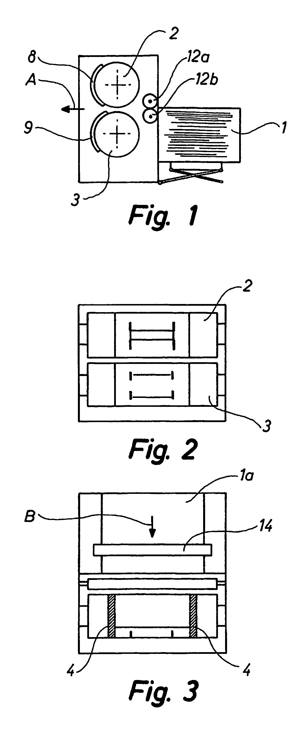
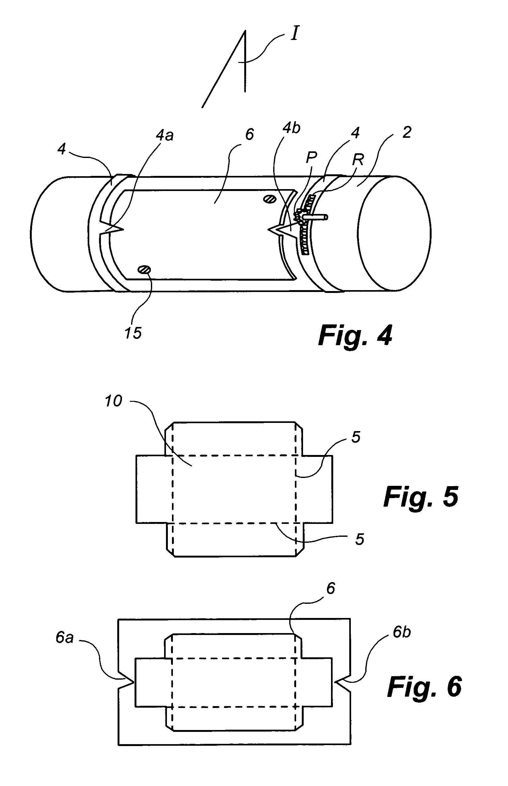
[0019]The machine shown in FIG. 1 is suited for punching blanks of corrugated cardboard out of a web of corrugated cardboard or plates thereof positioned in a corrugated cardboard supply 1. While the blanks are being punched out they are also being provided with folding lines. These lines can for instance be positioned as indicated by the dotted lines 5 in FIG. 5.

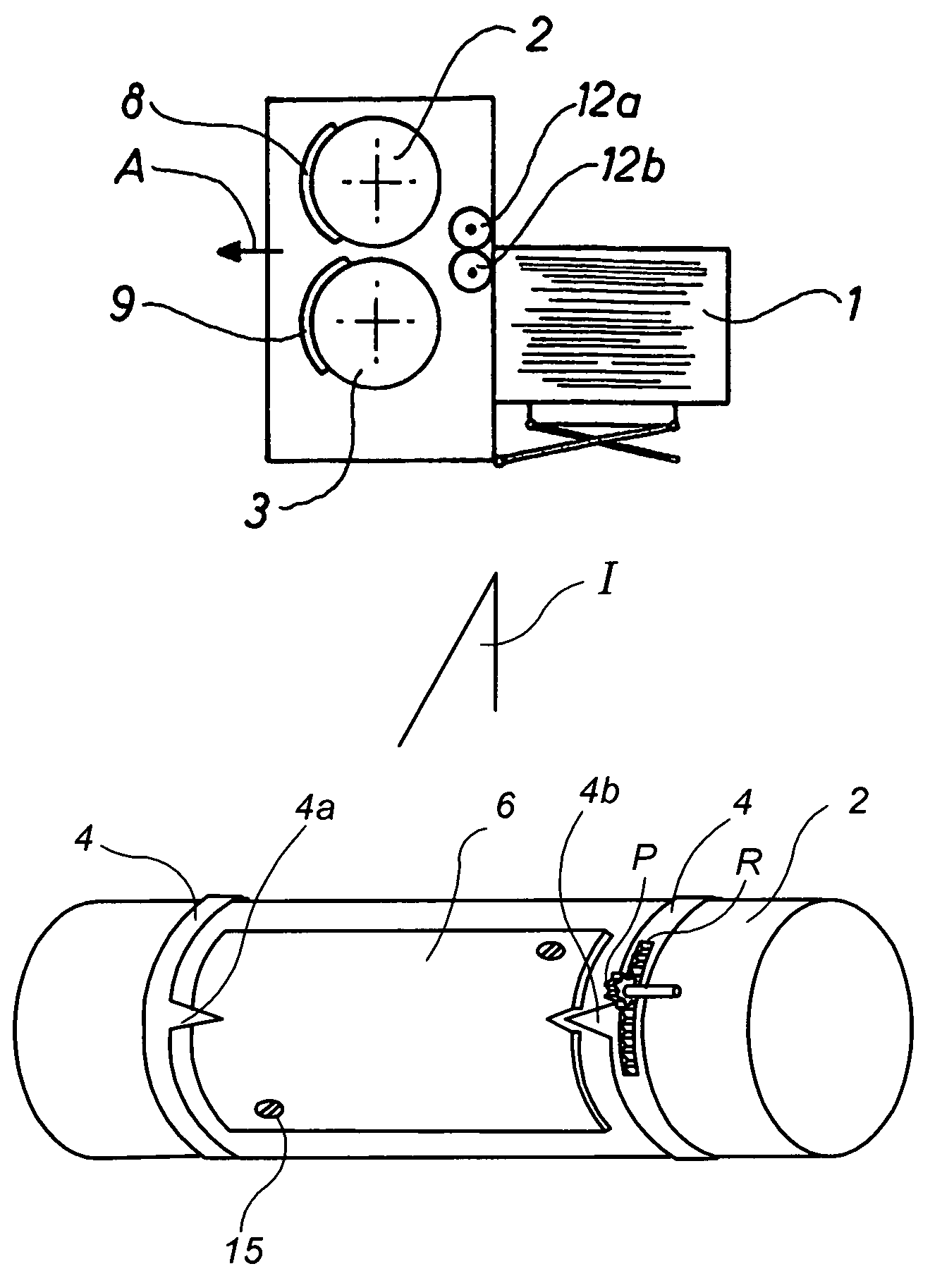
[0020]As shown in FIG. 2, the machine includes two cylinders 2, 3 rotating towards each other and of which at least one 2 or 3 is provided on the outer surface with a curved wooden plate 6, cf. FIG. 4. The above punching tool and folding line tool are mounted on said wooden plate by being pressed into slits in the concave surface of said wooden plate. As the punching tool and the folding line tool have different appearances depending on the different punching purposes, a particular wooden plate would have to be produced for every purpose, said particular wooden plate being provided with slits in the correct locations, viz. ...


PUM


Abstract

A machine for punching blanks (10) of corrugated cardboard out of a web or plates of corrugated cardboard and for forming folding lines (5) in said blanks. The machine has two cylinders (2, 3) rotating towards each other and of which at least one cylinder is provided on the outer surface with a curved wooden plate (6). The punching tools and the folding line tools (8, 9) are mounted on said wooden plate by being pressed into slits in said wooden plate (6). The cylinders (2, 3) are made of metal, preferably steel. The wooden plate (6) is secured to the cylinder (2, 3) by being screwed (15) thereon. The wooden plate is centered on the cylinder by means of two adjustable rings (4) on the cylinder. Each ring (4) is provided with an axially directed guide projection (4a, 4b) adapted to interact with an end notch (6a, 6b) in the wooden plate. In this way, it is rendered possible in a very simple way to centre the wooden plate and consequently the punching tool in relation to the vertical centre plane of the cylinder.

Description

[0001]This application is U.S. National stage filed under 35 U.S.C. 371 based on International Application PCT / IB03 / 00486 filed on Feb. 2, 2003; which claims priority from Denmark application No. PA 2002 00215 filed Feb. 13, 2002.TECHNICAL FIELD[0002]The present invention relates to a machine for punching blanks out of a web of corrugated cardboard and for forming folding lines in said blanks, said machine including two cylinders rotating towards each other and of which at least one cylinder is provided on the outer surface with a curved wooden plate, preferably made of plywood, punching tools and folding line tools being mounted on said wooden plate by being pressed into slits in said wooden plate.[0003]In the present application, the expression “wooden plate” is to be interpreted in very broad terms as the plate can also be made of plastics, optionally reinforced plastics.BACKGROUND ART[0004]U.S. Pat. Nos. 5,641,551 and 6,162,155 disclose a rotation punching machine is known which...

Claims


Application Information

Patent Timeline
Patent Type & Authority Patents(United States)
IPC IPC(8): B31B1/16B31B1/14B26D7/26B31B50/16B31B50/20B31B50/25B31B50/83
CPCB26D7/2614B31B1/20B31B1/24B31F1/10B31B1/25B26D2007/2607B31B2201/257B31B2201/143B31B2201/255B31B2201/908B31B50/83B31B50/146B31B50/254B31B50/256
Inventor JORNBORN, STEFANRYDBERG, TOMMY
Owner JORNBORN STEFAN
Learn More