
Utility cover system

a technology for utility covers and access structures, applied in thin material processing, artificial islands, construction, etc., can solve the problems of damage to the access structure, labor intensive and time-consuming, and damage to the components within the access structure, and achieve the effect of eliminating the need for expensive adjustment structures

Inactive Publication Date: 2006-02-07
CORR ROBERT F
View PDF20 Cites 20 Cited by
  • Summary
  • Abstract
  • Description
  • Claims
  • Application Information

AI Technical Summary

Benefits of technology

[0011]In view of the foregoing disadvantages inherent in the known types of utility access structures now present in the prior art, the present invention provides a new utility cover system construction wherein the same can be utilized for preventing water leakage into a utility entrance within a road surface and for eliminating the need for expensive adjustment structures.
[0016]A second object is to provide a utility cover system for preventing water leakage into a utility entrance within a road surface and for eliminating the need for expensive adjustment structures.
[0017]Another object is to provide a utility cover system that is rugged, flexible, lightweight, inexpensive and easy to handle.
[0019]A further object is to provide a utility cover system that absorbs vehicle impact and disperses vehicle weight thereby reducing damage to the utility access structure.
[0020]Another object is to provide a utility cover system that can be ground with the asphalt during a road-resurfacing project thereby reducing the amount of time and labor required to resurface a road.

Problems solved by technology

One of the problems with conventional utility access structures is that they allow surface water to flow into the access structures thereby damaging the components within the access structure.
Another problem is that when an asphalt road is resurfaced, an upper portion of the asphalt may be ground off which can cause damage to the access structure.
In addition, it is often times required that workers manually remove the asphalt surrounding the access structure which is labor intensive and time consuming.
To solve the resurfacing problem, adjustable structures (e.g. adjustment rings, etc.) have been created but they are extremely expensive and noisy for surrounding residents.
While these devices may be suitable for the particular purpose to which they address, they are not as suitable for preventing water leakage into a utility entrance within a road surface and for eliminating the need for expensive adjustment structures.
Conventional utility access structures are prone to water leakage and interfere with road resurfacing.

Method used


Image

  • Utility cover system
  • Utility cover system
  • Utility cover system

Examples


Embodiment Construction

A. Overview

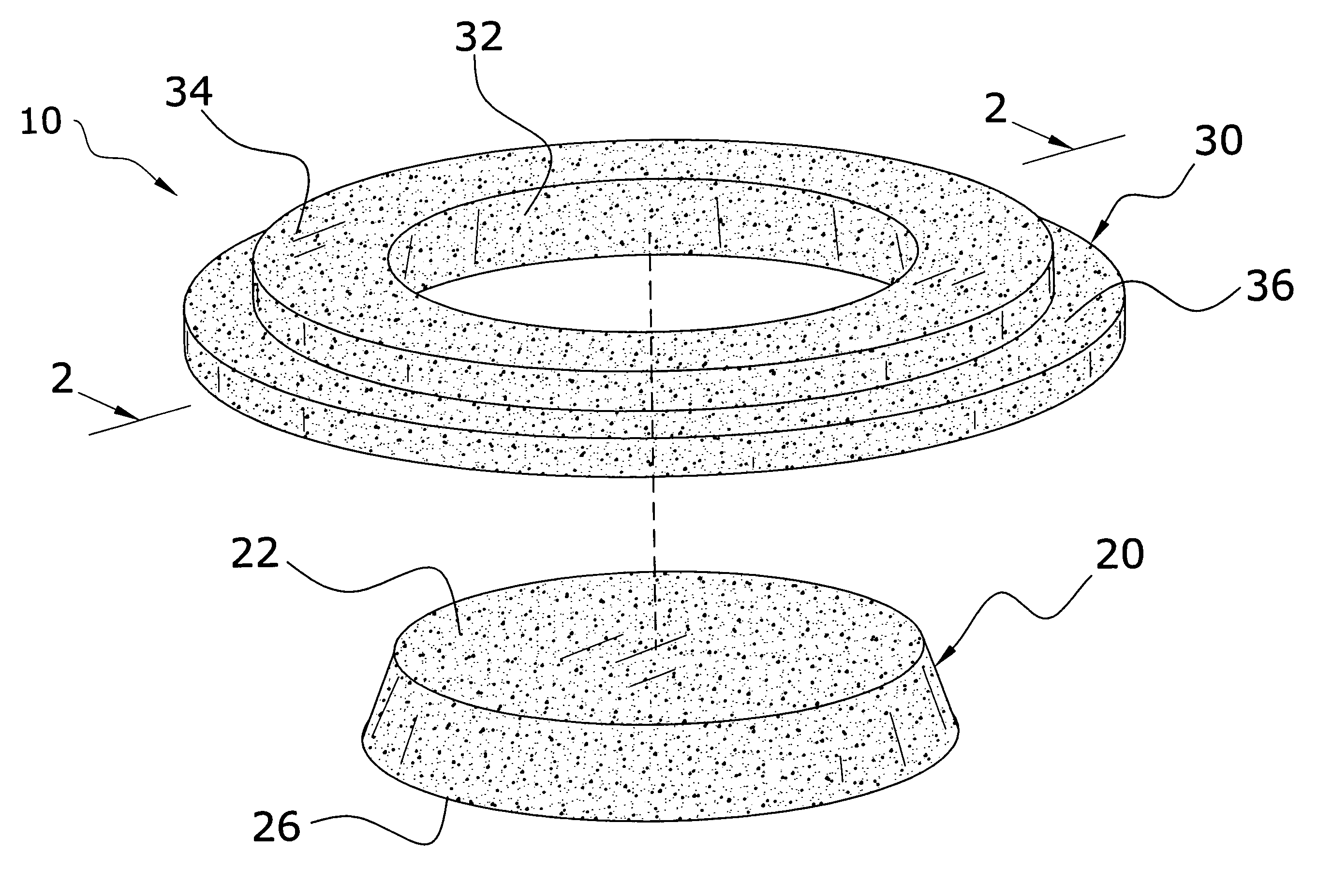
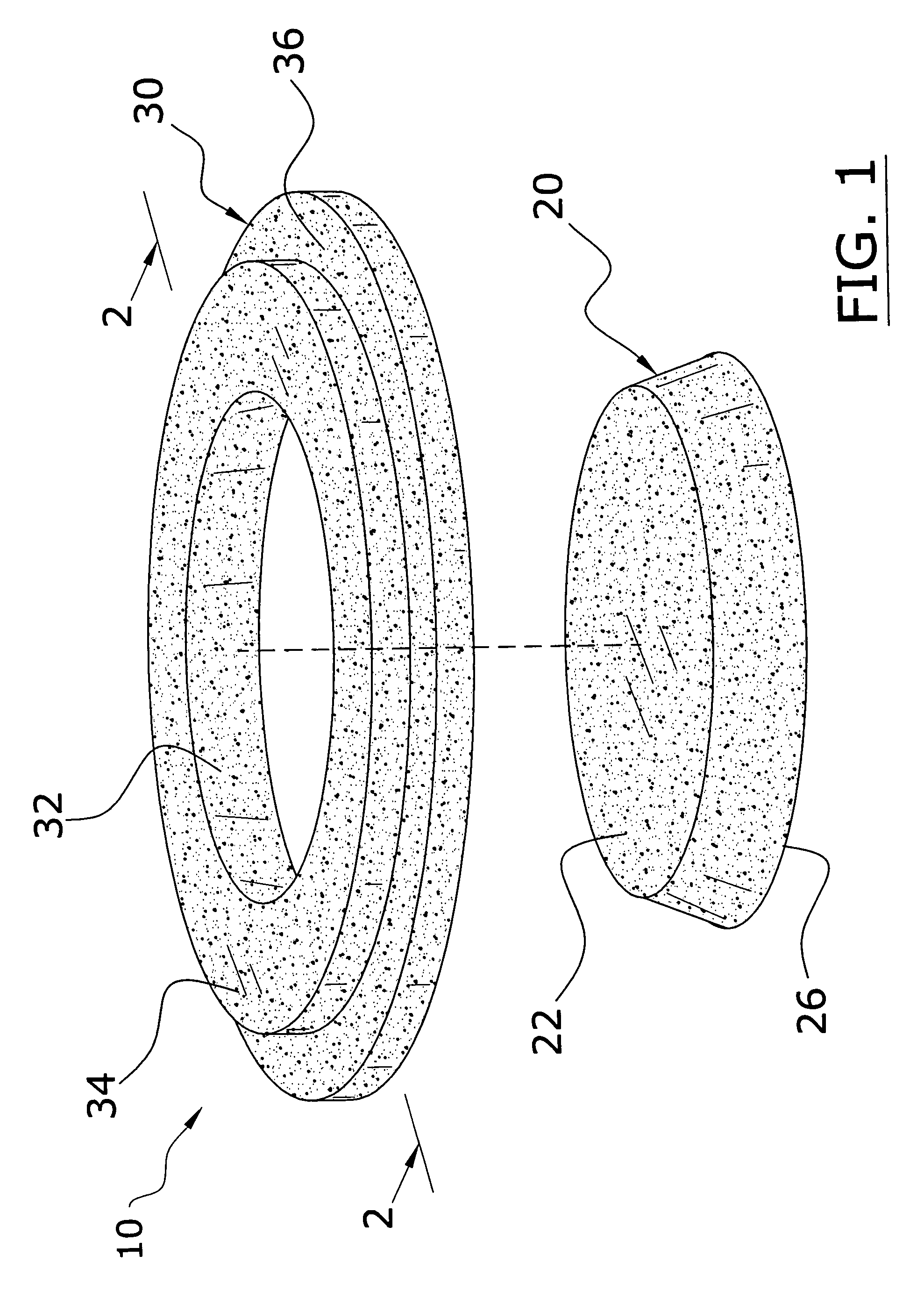
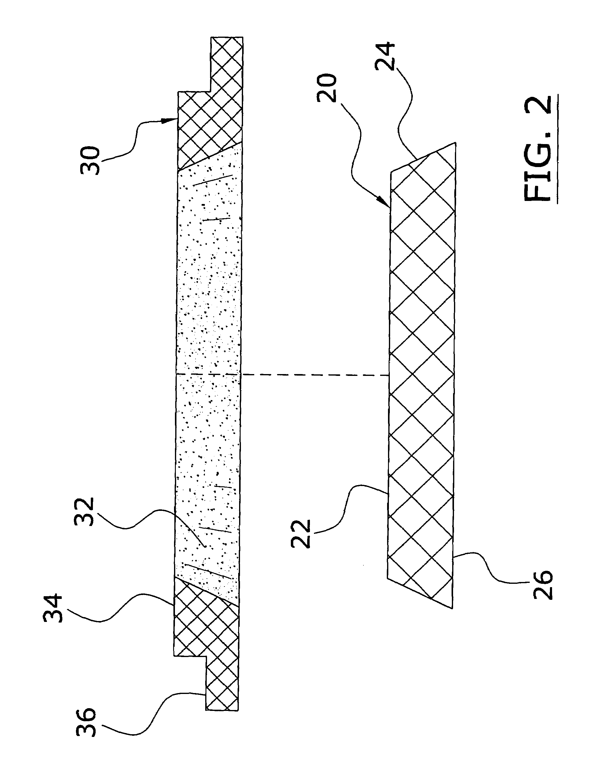
[0034]Turning now descriptively to the drawings, in which similar reference characters denote similar elements throughout the several views, FIGS. 1 through 7 illustrate a utility cover system 10, which comprises an outer frame 30 having an opening defined by an inner tapered edge 32, and a wedge cover 20 having an outer tapered edge 24 that fits within the opening of the outer frame 30. The outer frame 30 preferably has an inner segment 34 and an outer segment 36, wherein the outer segment 36 is thinner than the inner segment 34.

B. Outer Frame

[0035]The outer frame 30 has an opening defined by an inner tapered edge 32 as best illustrated in FIGS. 1 and 3 of the drawings. The outer frame 30 may have various shapes such as but not limited to rectangular, circular and the like. The outer frame 30 preferably has an inner segment 34 and an outer segment 36 as shown in FIGS. 1 and 3 of the drawings.

[0036]The outer frame 30 is preferably comprised of a resilient and flexible mat...


PUM


Abstract

A utility cover system for preventing water and silt leakage into a utility entrance within a road surface. The utility cover system includes an outer frame having an opening defined by an inner tapered edge, and a wedge cover having an outer tapered edge that fits within the opening of the outer frame. The outer frame preferably has an inner segment and an outer segment, wherein the outer segment is thinner than the inner segment.

Description

CROSS REFERENCE TO RELATED APPLICATIONS[0001]Not applicable to this application.STATEMENT REGARDING FEDERALLY SPONSORED RESEARCH OR DEVELOPMENT[0002]Not applicable to this application.BACKGROUND OF THE INVENTION[0003]1. Field of the Invention[0004]The present invention relates generally to utility access structures positioned within asphalt or concrete roads and more specifically it relates to a utility cover system for preventing water leakage into a utility access structure within a road surface and for eliminating the need for expensive adjustment structures.[0005]2. Description of the Related Art[0006]Utility access structures have been in use for years for various utilizes such as utility valves (e.g. valve covers), sewers (e.g. manholes) and catch basins. The utility access structures typically have a housing structure positioned within the road surface with a cover removably attached thereto. The housing structure and the cover are typically comprised of a hard material such ...

Claims


Application Information

Patent Timeline
IPC IPC(8): E02D29/14
CPCE02D29/14Y10T137/7021
Inventor CORR, ROBERT F.
Owner CORR ROBERT F
Learn More