
Vehicle external mirror wiring integration

a technology for wiring and mirrors, applied in the field of vehicle external mirrors, can solve the problems of increasing complexity and cost of mirror assembly, excessive deformation or breakdown of foam, etc., and achieve the effect of reducing complexity

Inactive Publication Date: 2006-02-07
SCHEFENACKER VISION SYST AUSTRALIA
View PDF4 Cites 4 Cited by
  • Summary
  • Abstract
  • Description
  • Claims
  • Application Information

AI Technical Summary

Benefits of technology

[0002]Many different mirror housing assemblies constructions are known. A new mirror construction is disclosed in the applicant's earlier International Patent Application No PCT / AU00 / 00054. The invention disclosed in the above-mentioned International application uses a thin moulded external plastic shell in conjunction with a foam core to form a mirror housing or mirror head. In order to reduce weight and cost, it is desirable to reduce the foam density. At lower densities however, stresses within the foam can cause excessive deformation or breakdown of the foam. A solution to this problem is provided by the applicant's above-mentioned International application which discloses a load diffuser extending laterally into the foam core. Such a load diffuser enables reduction of stresses within the foam.
[0007]It is desirable that pivot mechanisms be as compact as possible and as self contained as possible so that assembly of a mirror is facilitated and that portion of a mirror assembly taken up by the pivot is as small as possible.
[0008]It is also desirable in many mirror configurations that the mirror sweep over the pivot mechanism and hence having a pivot mechanism as small as possible is also desirable.
[0011]It is an object of the invention to provide a mirror assembly of reduced complexity.

Problems solved by technology

At lower densities however, stresses within the foam can cause excessive deformation or breakdown of the foam.
While problems can arise with all mirror assembly configurations, the problem becomes more acute where there are necked regions and where pivot connectors are used to allow the head to pivot with respect to the base.
Provision of a mirror wiring harness and the need to accommodate such a harness within and through the mirror assembly adds complexity and cost to the mirror assembly.

Method used


Image

  • Vehicle external mirror wiring integration
  • Vehicle external mirror wiring integration
  • Vehicle external mirror wiring integration

Examples


first embodiment

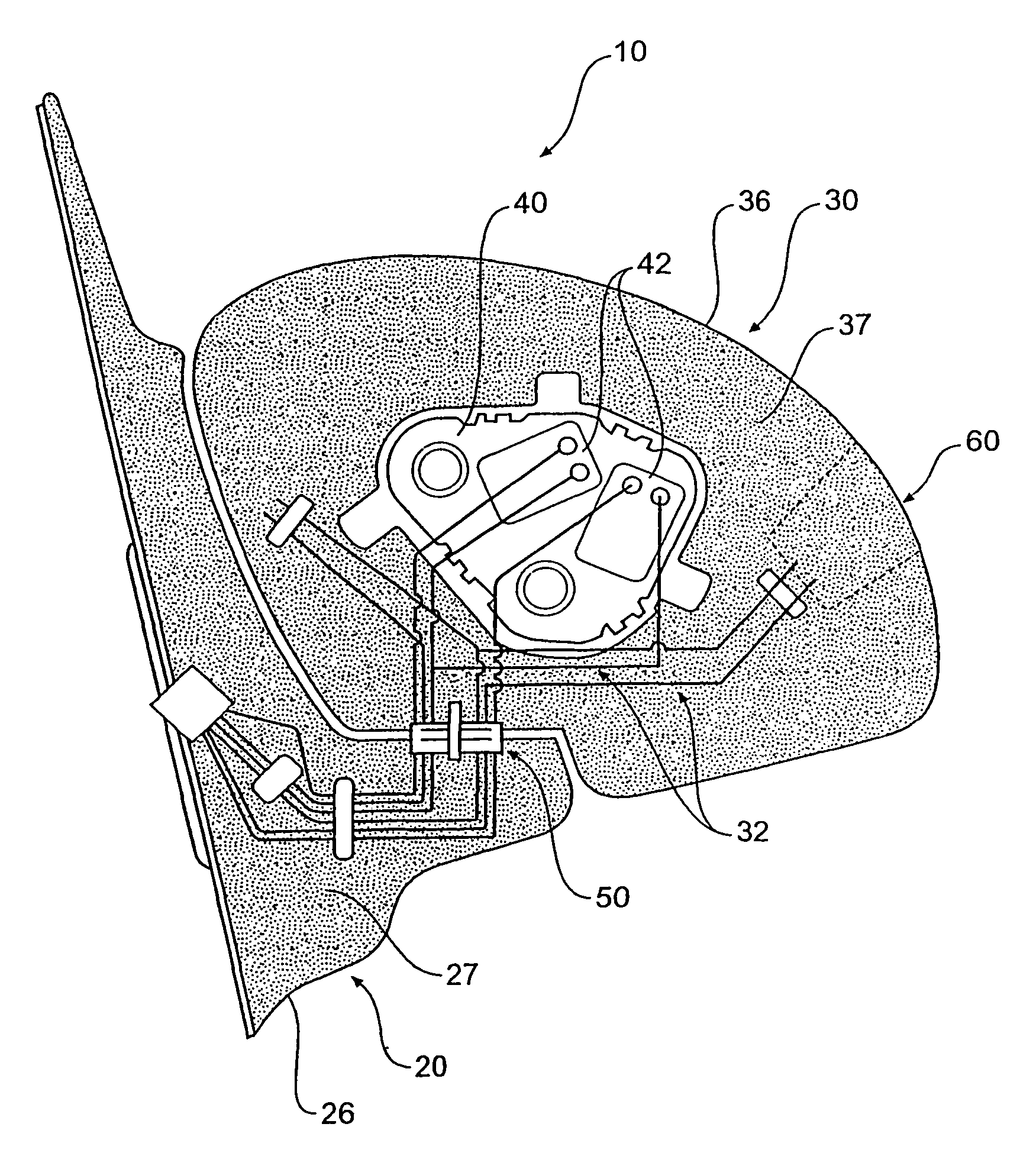
[0059]FIG. 1 shows a schematic view from the rear of a vehicle external mirror assembly in accordance with the invention;

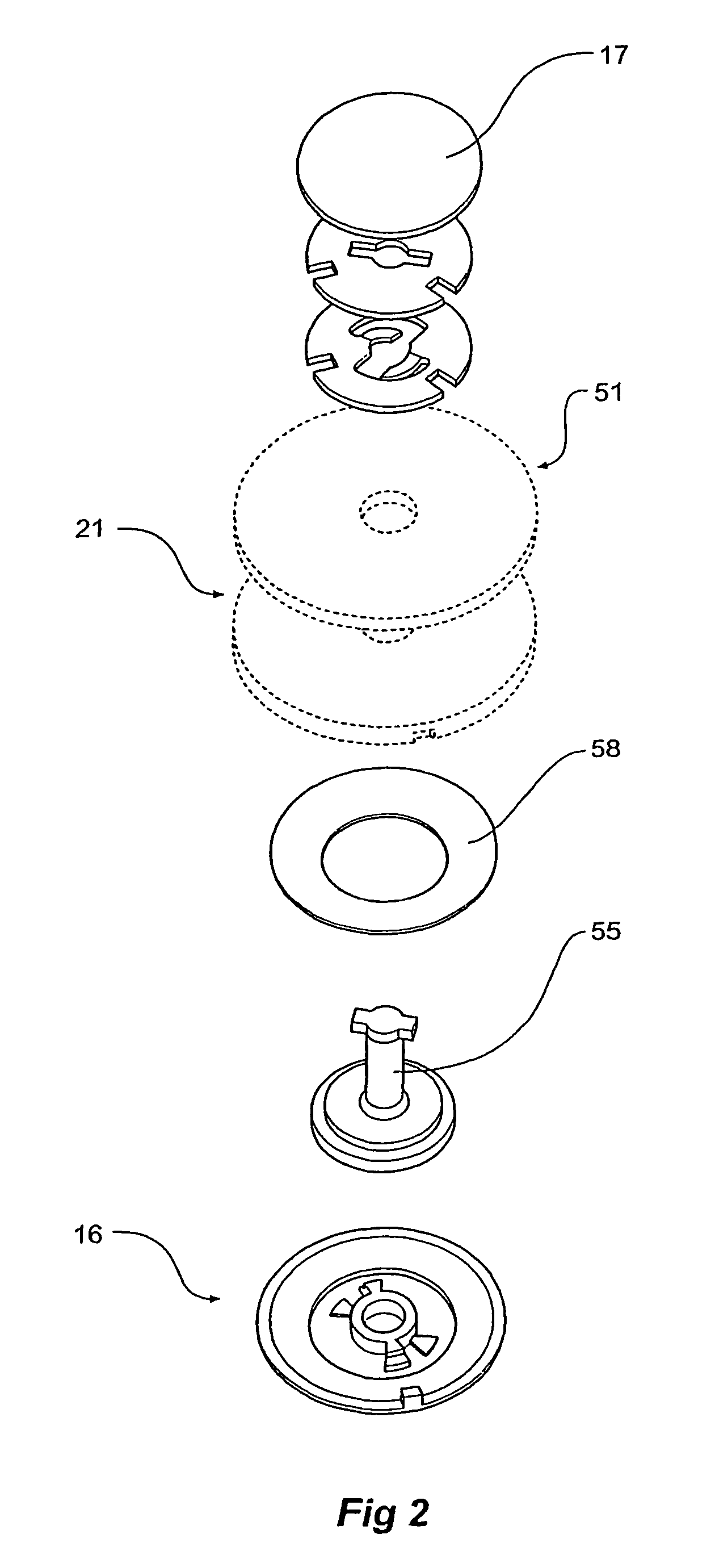
[0060]FIG. 2 shows the pivot assembly of the mirror assembly of FIG. 1 in an exploded view;

[0061]FIG. 3 shows further details of the pivot assembly of FIG. 2 in an exploded perspective view;

[0062]FIG. 4a, shows a sub-assembly of the assembly of FIG. 1;

[0063]FIGS. 4b and 4c show an alternative sub-assembly to that shown in FIG. 4a.

[0064]FIG. 5 shows a sub-assembly of the assembly of FIGS. 4a, 4b and 4c;

[0065]FIG. 6 shows an exploded view of the assembly of FIG. 1.

second embodiment

[0066]FIG. 7 in a schematic view from the rear of a vehicle external mirror assembly in accordance with the invention

[0067]Referring to FIG. 1, a vehicle external mirror assembly 10 comprises a head 30 mounted to a base 20. A pivot connector 50 is provided to connect the base 20 to the head 30 in such a way as to allow respective pivotal movement.

[0068]The mirror head 30 comprises an external shell 36 which is filled with foam 37. A motor mechanism 40 is held within the mirror head 30 by the foam 37. The motor mechanism 40 supports a mirror (not shown) and provides a means for changing the angle of the mirror with respect to the head. More specifically, motors 42, powered by the electrical system of the vehicle, drive the mirror about substantially horizontal and substantially vertical axes to enable the driver to adjust his or her rear view. FIG. 6 shows an exploded view of the final assembly.

[0069]The mirror head 30 is also provided with an electrical accessory receptacle 60. This...


PUM


Abstract

A vehicle external mirror assembly (10) comprising a mirror head (30) adapted to support a mirror, the mirror head (30) having an external shell (36), a first foam core (37) providing support for the shell (36), a mirror base (20) adapted for mounting to a vehicle, the mirror base (20) connected to the mirror head (30) or integral with the mirror head (30) and a plurality of electrical conductors (32) disposed within the first foam core (37), the conductors (32) are arranged and constructed to diffuse stress within the foam core (37).

Description

[0001]The present invention relates to vehicle external mirrors an in particular to vehicle external mirrors having an external shell supported by a foam core.[0002]Many different mirror housing assemblies constructions are known. A new mirror construction is disclosed in the applicant's earlier International Patent Application No PCT / AU00 / 00054. The invention disclosed in the above-mentioned International application uses a thin moulded external plastic shell in conjunction with a foam core to form a mirror housing or mirror head. In order to reduce weight and cost, it is desirable to reduce the foam density. At lower densities however, stresses within the foam can cause excessive deformation or breakdown of the foam. A solution to this problem is provided by the applicant's above-mentioned International application which discloses a load diffuser extending laterally into the foam core. Such a load diffuser enables reduction of stresses within the foam.[0003]Mirror assemblies and i...

Claims


Application Information

Patent Timeline
Patent Type & Authority Patents(United States)
IPC IPC(8): G02B7/182B60R1/072B60R1/06B60R1/07
CPCB60R1/07B60R1/06B60R1/072
Inventor SCHUURMANS, MAARTEN JOHANNESGILBERT, ROBERT WILLIAM
Owner SCHEFENACKER VISION SYST AUSTRALIA
Learn More