Diagnostic readout for operation of a crane

Active Publication Date: 2006-02-07
RAMSEY IND INC +4
View PDF20 Cites 35 Cited by
  • Summary
  • Abstract
  • Description
  • Claims
  • Application Information

AI Technical Summary

Benefits of technology

[0008]In accordance with the principles and concepts of the invention, there is disclosed a control system for a crane that displays status codes of the operation of the crane apparatus. The operator of the crane can take appropriate action based on the status code, rather than have to assimilate the crane operation itself in order to make a mental diagnosis of the condition of the crane. In accordance with another feature of the invention, the control system monitors the hydraulic pressure of the crane lift mechanism, and prevents certain actions by the operator in order to maintain safe operational limits of the crane, and a safe environment for personnel in the vicinity of the crane.
[0010]An important aspect of the invention is the use of a pressure transducer coupled to a lift cylinder of the crane to monitor the extent of the load on the boom of the crane. The analog signal from the pressure transducer is processed by the control system. The operation of the crane is controlled, based on the pressure indication. The processor in the control system is programmed to define different pressure ranges, and corresponding actions to take, together with the input commands by the operator, to efficiently and safely operate the crane to produce the results desired by the operator.
[0012]In accordance with yet another feature of the invention, the control system is constructed to operate with a wireless transmitter. The wireless transmitter has a number of switches and buttons for transmitting coded signals to the receiver portion of the control system. The operator can thus control the operations of the crane, visually observe the status codes provided by the control system, and make expedited and accurate decisions for moving the crane apparatus to safely achieve the desired results.

Problems solved by technology

When an overload condition is sensed, by the pressure exceeding a predefined amount, the various actions of the crane are automatically limited or stopped, and those not allowed but nevertheless requested by the operator are denied.

Method used


Image

  • Diagnostic readout for operation of a crane
  • Diagnostic readout for operation of a crane
  • Diagnostic readout for operation of a crane

Examples


Embodiment Construction

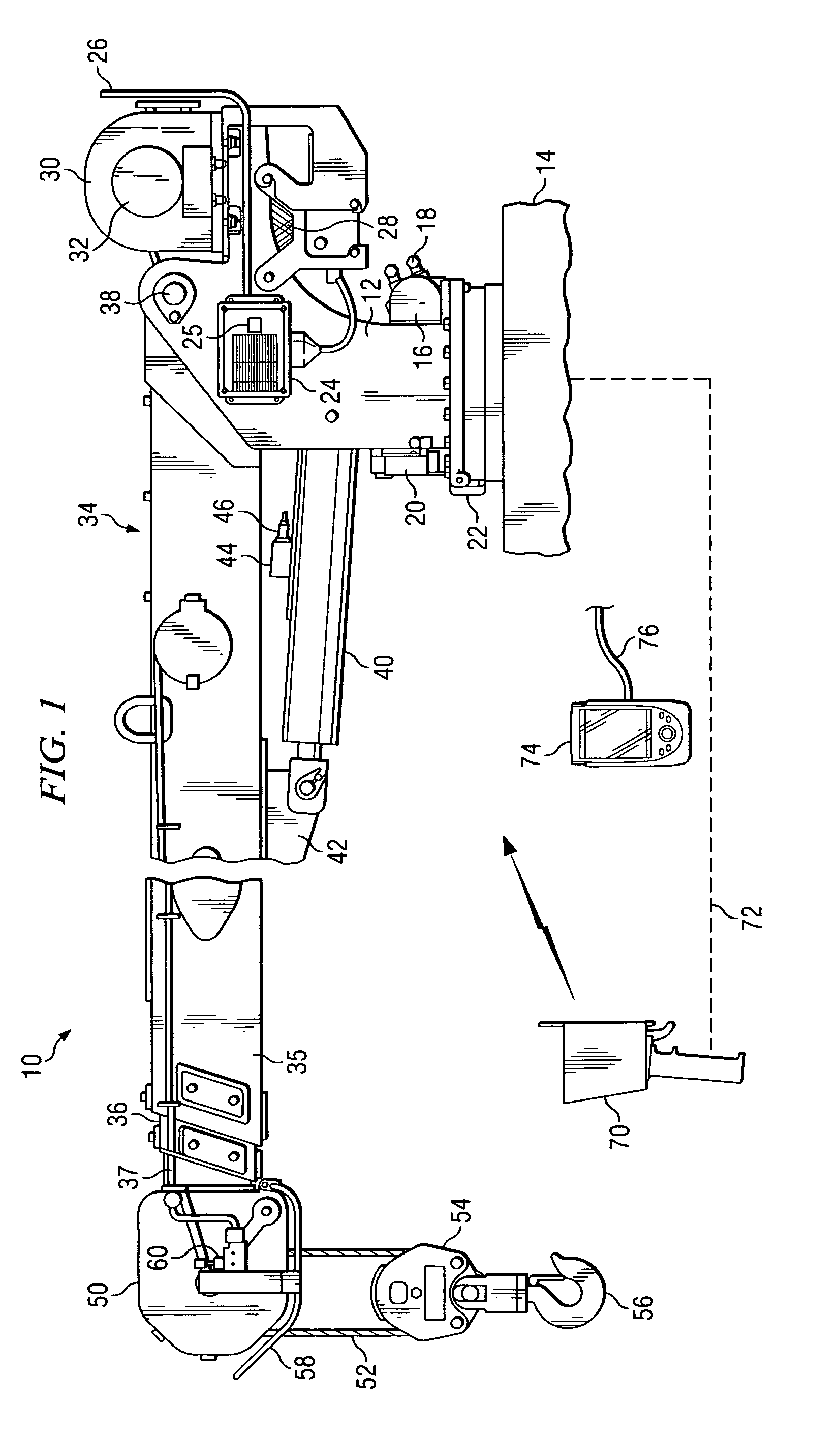
[0025]With reference to FIG. 1, there is shown a stiff arm type of crane 10 in which the invention can be advantageously practiced. The crane 10 includes a swivel pedestal assembly 12 mounted for rotational movement to a platform 14. The platform can be a truck bed, another type of vehicle, or a stationary platform. The invention is well adapted for use as a truck-mounted service crane. The pedestal assembly is rotatable by the use of gears of a conventional type and a hydraulic motor 16 to which high pressure hydraulic connections 18 are fixed. As will be described more fully below, the pedestal assembly 12 is rotatable through 370 degrees. This limited rotation allows hydraulic and electrical cables to be routed through the central cylindrical portion of the pedestal assembly 12.

[0026]Mounted to the pedestal assembly 12 is a magnetic home sensor switch 22 and corresponding switch mechanism 20 for sensing the rotational position of the pedestal assembly 12, namely a 0° position and...


PUM


Abstract

A programmable control system for a crane that senses a hydraulic pressure of the lift mechanism, and controls the movements of the crane apparatus as a function of the magnitude of the hydraulic pressure. As the status conditions of the crane change, sense switches relay such information to a programmable controller and error codes are generated and presented to the operator. The control system can respond to the states of the sense switches and override wireless command inputs to the control system.

Description

BACKGROUND OF THE INVENTION[0001]Cranes are typically used to lift and / or relocate loads from one location to another. Generally, cranes are used to lift or lower loads between a ground level or from a transport vehicle to a different elevation. In other applications, cranes are used to relocate loads from one location, such as a cargo carrier to a land vehicle. In all applications of the use of cranes, a load is generally lifted by a hook mechanism suspended by a cable at the end of a boom. The boom can be lifted vertically and rotated from side to side to move the load to a variety of horizontal and vertical locations.[0002]The operation of a crane requires a high degree of skill so that the loads can be moved efficiently and safely. The safe operation of a crane is especially important when mounted to a mobile vehicle, such as a truck. In this situation, if the load is heavy and extended horizontally too far from the truck, the crane will overbalance the vehicle and cause it to t...

Claims


Application Information

Patent Timeline
IPC IPC(8): B66C15/00
CPCB66C23/905
Inventor EDGAR, II, ROBERT A.NOBLES, RANDALL J.
Owner RAMSEY IND INC
Why Eureka
Try Eureka