Controller of data recorder

a data recorder and control board technology, applied in the field of control boards of data recorders, can solve the problems of data amount ultimately becoming null, buffer memory becoming empty, data recording on optical disc interruption,

Inactive Publication Date: 2006-01-31
SEMICON COMPONENTS IND LLC
View PDF67 Cites 14 Cited by
  • Summary
  • Abstract
  • Description
  • Claims
  • Application Information

AI Technical Summary

Benefits of technology

[0010]It is an object of the present invention to provide a controller of a data recorder that records data in a manner that the continuity of the data is ensured even if the recording of data to a recording medium is interrupted.

Problems solved by technology

If the decrease continues, the data amount ultimately becomes null and the buffer memory becomes empty.
This stops the stream of data to the encoder and causes an interruption in the data recorded on the optical disc.
Data is recorded on an optical disc using a recording technique that designates the file group recorded on the optical disc (e.g., disc at once, track at once) Thus, if a buffer underrun error occurs, the entire optical disc becomes unusable when employing disc at once, and the track undergoing recording becomes unusable when employing track at once.
This has increased the tendency of the occurrence of buffer underrun errors.
The link blocks decrease the recording capacity of the optical disc.
Further, there are CD-ROM drives that are not capable of handling packet writing.
Such CD-ROM drives cannot reproduce data written to optical discs through packet writing.
For example, packet writing cannot be applied for a CD-DA player.
Thus, a CD-R drive cannot record CD-DA audio data through packet writing.
However, when a buffer underrun error occurs, the data file that was being recorded before the occurrence of the buffer underrun error must be recorded again.
This wastes the recording performed prior to the occurrence of the buffer underrun error and increases the recording time.
However, MD drives have the same problem as CD-RW drives.

Method used


Image

  • Controller of data recorder
  • Controller of data recorder
  • Controller of data recorder

Examples


Embodiment Construction

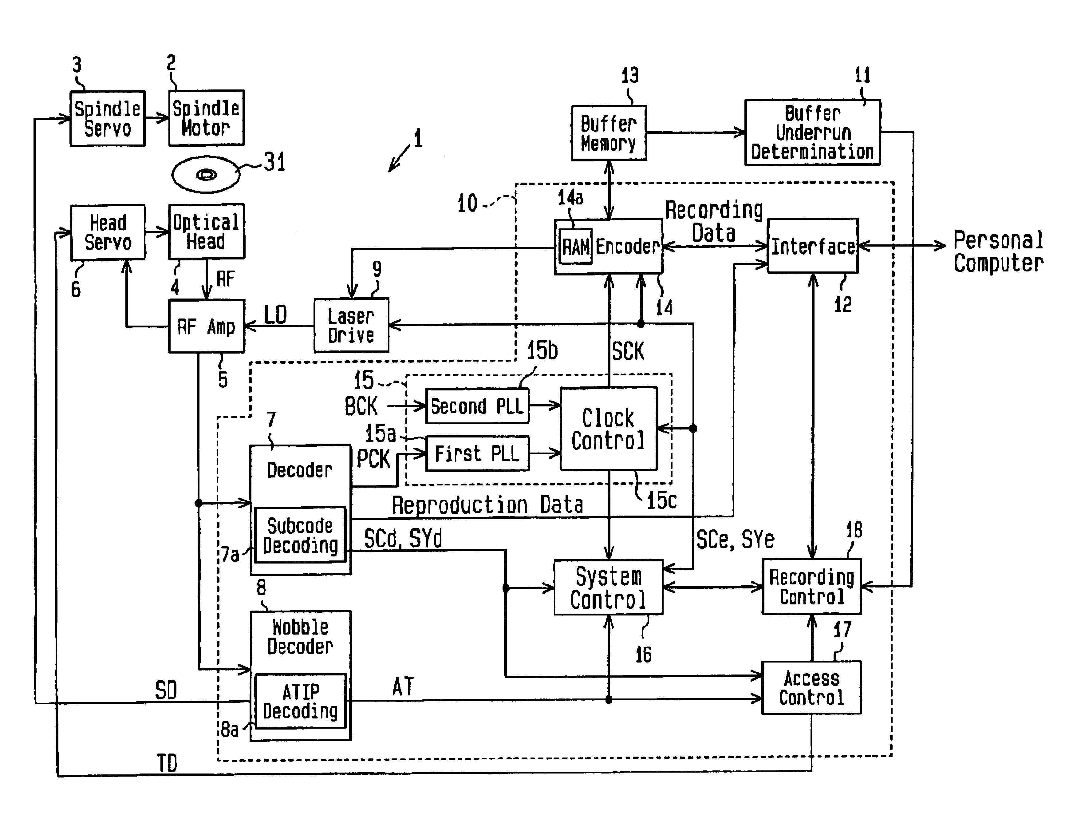
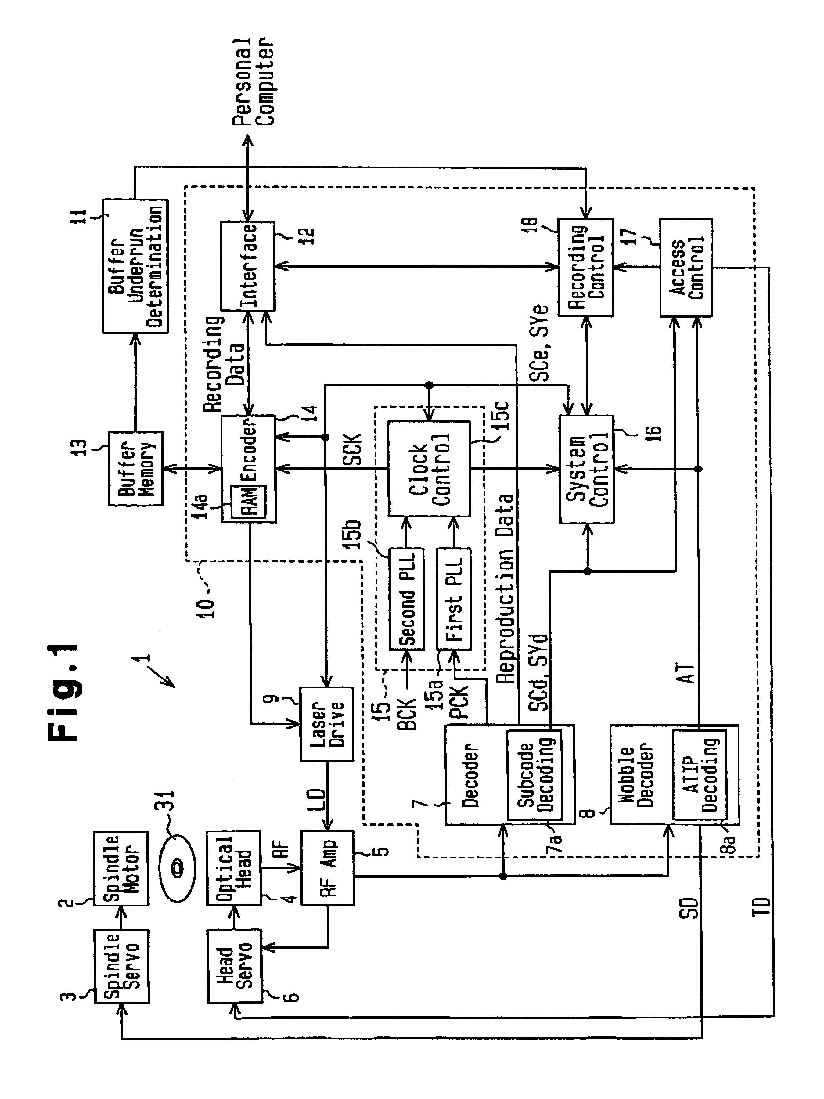
[0019]FIG. 1 is a schematic block diagram of a CD-R drive 1, which functions as a disc recording system, employing a data recorder controller according to a preferred embodiment of the present invention. As shown in FIG. 1, the CD-R drive 1 has a recording controller 10, which includes a decoder 7, a wobble decoder 8, and interface 12, an encoder 14, a clock generator 15, a system control circuit 16, an access control circuit 17, and a recording control circuit 18.

[0020]In addition to the recording controller 10, the CD-R drive 1 includes a spindle motor 2, a spindle servo circuit 3, an optical head 4, an RF amplifier 5, a head servo circuit 6, a laser drive circuit 9, a buffer underrun determination circuit 11, and a buffer memory (RAM) 13.

[0021]The CD-R drive 1 is connected to a personal computer via the external connection terminal 11 to record data, which is provided from the personal computer, on an optical disc 31 that complies with the CD-R standards. Further, the CD-R drive ...


PUM

PropertyMeasurementUnit
frequencyaaaaaaaaaa
data transmission rateaaaaaaaaaa
transmission rateaaaaaaaaaa

Abstract

A controller of a data recorder that records data on a recording medium such that the occurrence of buffer underrun errors are prevented. Data encoded by an encoder is recorded on the recording medium. A decoder decodes the data recorded on the recording medium. The data recorder interrupts the recording of data when a buffer underrun is likely to occur. The controller restarts the recording of data when the decoded data and the encoded data are synchronized. When the decoded data is delayed from the encoded data, the controller stops the encoding until the decoded data catches up with the encoded data.

Description

BACKGROUND OF THE INVENTION[0001]The present invention relates to a controller of a data recorder, and more particularly, to a data recorder controller for controlling the recording of data in a data recorder, which writes data to a medium.[0002]An optical disc recorder records data on an optical disc, which serves as a recording medium. A CD-DA family compact disc-recordable (CD-R) drive is one type of optical disc recorder that is widely used. A CD-R is a so-called write-once optical disc on which data is written only once. The recorded data cannot be physically deleted. A laser beam is irradiated against the optical disc from an optical head of the CD-R drive. The heat of the laser beam melts a dye and forms recording pits on a recording layer of the optical disc. Data is recorded on the disc by changing the reflecting rate of the recording layer.[0003]The optical disc recorder includes a buffer memory and an encoder. The buffer memory temporarily stores data provided from an ext...

Claims


Application Information

Patent Timeline
Patent Type & Authority Patents(United States)
IPC IPC(8): G11B20/10G11B7/00G11B19/04G11B20/14G11B27/19G11B27/24G11B27/30
CPCG11B19/04G11B20/10G11B20/1403G11B27/19G11B2220/2545G11B27/3063G11B2020/1062G11B2020/10814G11B2220/218G11B27/24
Inventor HAYASHI, KOJITSUKIHASHI, AKIRAHANAMOTO, YASUSHITANAKA, TOHRU
Owner SEMICON COMPONENTS IND LLC
Why Eureka
Try Eureka