Bill validator

Inactive Publication Date: 2006-01-31
PANASONIC CORP
View PDF9 Cites 11 Cited by
  • Summary
  • Abstract
  • Description
  • Claims
  • Application Information

AI Technical Summary

Benefits of technology

[0044]In accordance with also an aspect of this invention, the bill validator has a pair of blocking gates disposed such that the cross-sectional surfaces of the blocking gates are positioned to form a rotational symmetry with each other. The configuration has an effect to reduce the production cost of the validator by adopting blocking gates with same shapes for common use.
[0044]In accordance with also an aspect of this invention, the bill validator has a pair of blocking gates disposed such that the cross-sectional surfaces of the blocking gates are positioned to form a rotational symmetry with each other. The configuration has an effect to reduce the production cost of the validator by adopting blocking gates with same shapes for common use.
[0045]In accordance with also an aspect of this invention, the bill validator has blocking gates having cylindrical periphery of a plurality of different shapes and concaved portions having shapes copying the cylindrical periphery in the pathway to dispose the blocking gate. The configuration can prevent the comb-shaped joint portion from jamming with bills.
[0046]In accordance with another aspect of this invention, the bill validator has a pair of blocking gates disposed such that the maximum peripheral surface of one blocking gate faces against the minimum peripheral surface of another blocking gate. The configuration can prevent joint portions of both blocking gates from jamming with bills and can dispose blocking gates within a close distance resulting a downsizing design of the validator.
[0047]In accordance with another aspect of this invention, the bill validator is provided with a driving portion to restrict the rotation of the blocking gates in one direction only. The configuration can prevent bills from being retrieved from the validator by a strong pulling force through a string or the like attached to the bill that makes blocking gates rotate in a reverse direction and eventually open the pathway.
[0050]In accordance with also an aspect of this invention, the bill validator is provided with a hook wheel on the rotary shaft coupled to the transportation portion, wherein a stopper to restrict the transportation portion by engaging with hook wheel, when the gear clutch is engaged in the other rotary shaft, is incorporated with the gear clutch. The configuration has an effect to eliminate risks that movement of bills can not be controlled under out-of-control movement of the transportation portion, even in a case when the power supply is changed by the gear clutch.
[0051]In accordance with also an aspect of this invention, the bill validator employs a ratchet mechanism driven by a solenoid as the driving portion, wherein the ratchet mechanism works also as a control portion. The configuration can provide a simple and reliable driving portion for the blocking gates.

Problems solved by technology

A typical fraudulent activity is to retrieve a bill by pulling a string or a tape attached to the bill out of the machine after vending goods or services.
But the problem is that the validator including the drum shaped body becomes large and the power consumed in the driving apparatus increases.

Method used


Image

  • Bill validator
  • Bill validator
  • Bill validator

Examples


Embodiment Construction

(Exemplary Embodiment)

[0019]Now, the exemplary embodiment of the present invention is described with reference to the drawings.

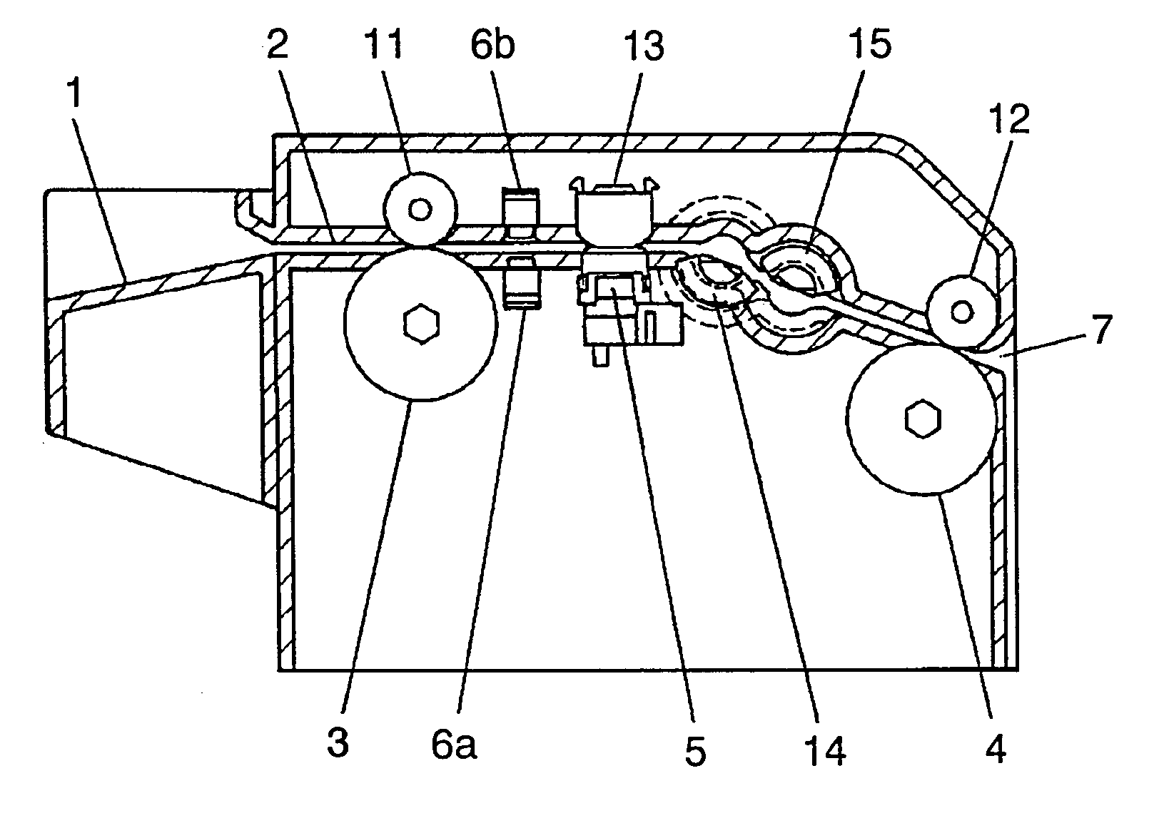
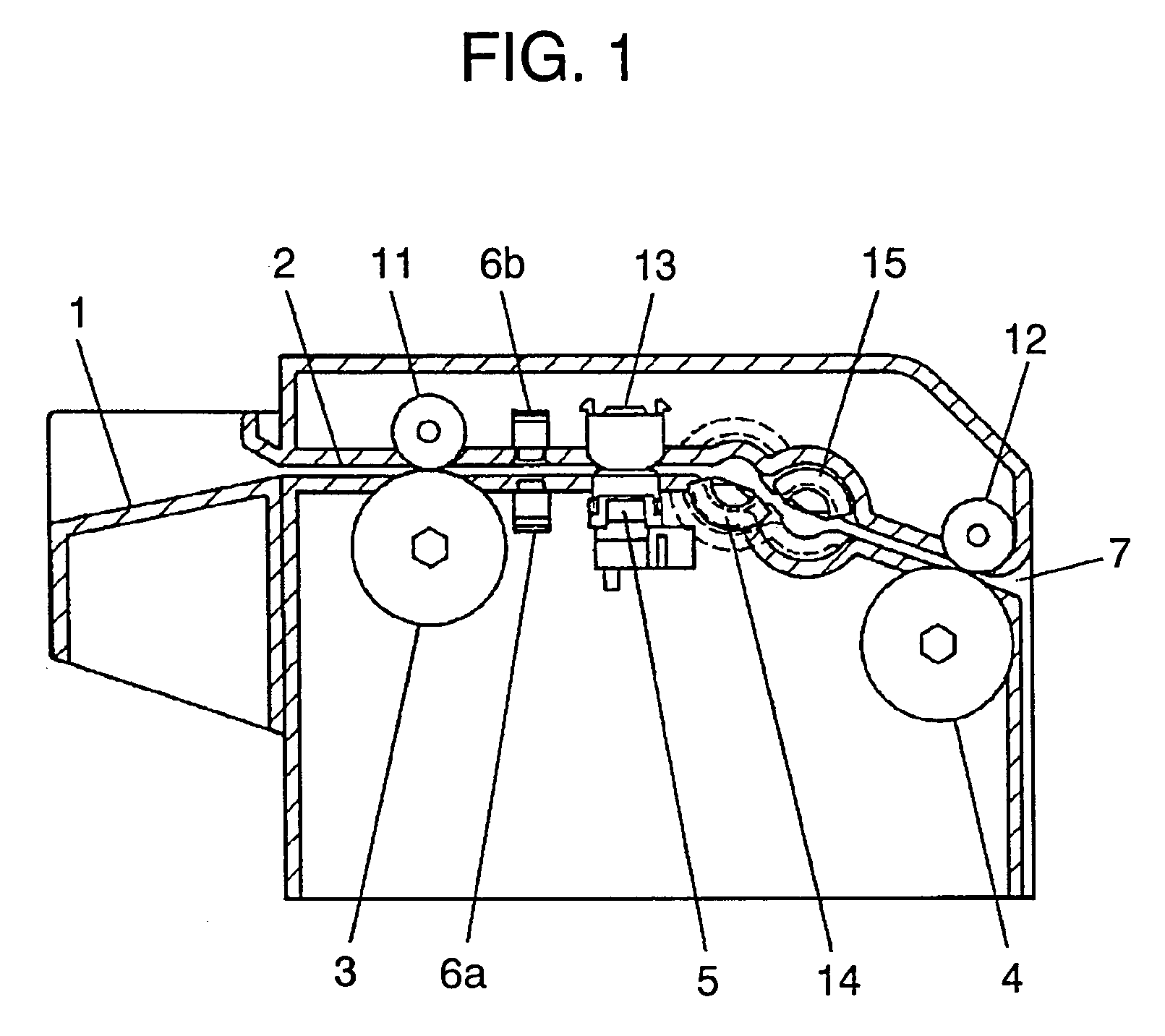
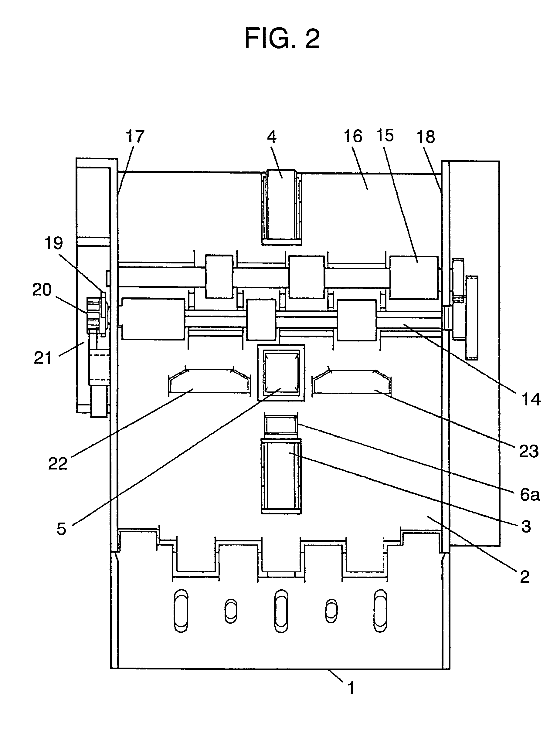
[0020]FIG. 1 shows a cross-sectional view of a pathway of the bill validator used in the exemplary embodiment of the present invention. Bill inlet 1 is coupled to pathway 2 provided with first transportation portion 3 and second transportation portion 4 as shown in FIG. 1. Rubber rollers accompanied by auxiliary rollers 11 and 12 respectively, facing each other across pathway 2 to press a bill between them are adopted as the transportation means in this example. Additionally, validation means comprised of magnetic sensor 5 with bill pressing member 13 and first optical sensors 6a and 6b are disposed in pathway 2.

[0021]Outlet 7 is located at an end of pathway 2 that extends to a bill storage box. Laid down across pathway 2, approximately semi-cylindrical shaped first blocking gate 14 and second blocking gate 15, a plurality of pathway selectors are disposed i...


PUM


Abstract

The bill validator disclosed is provided with a plurality of pathway selectors at a position nearer to the inlet than the outlet, wherein the selectors select the pathways in respective different phases for the pathways to form a cross between the plurality of pathway selectors in every pathway selection.

Description

FIELD OF THE INVENTION[0001]The present invention relates to a bill validator for use in automatic vending machine or gaming machine for testing the validity of a bill.BACKGROUND ART[0002]Modernized automatic vending machine or gaming machine or the like capable of operating with a bill in addition to the previously known coin or token is increasing recently. Though these machines are equipped with bill validators, machines served in unattended environment must have functions to prevent various fraudulent or criminal activities other than validation / discrimination of paper currency.[0003]A typical fraudulent activity is to retrieve a bill by pulling a string or a tape attached to the bill out of the machine after vending goods or services. To countermeasure such “stringing” activity a conventional bill validator is typically disposed with a block gate secured rotatably in a pathway to prevent bills from being retrieved.[0004]Now, a conventional bill validator is described with refer...

Claims


Application Information

Patent Timeline
IPC IPC(8): G07F7/04G07D9/00B65H5/38G07D7/00G07D7/12G07D11/00
CPCG07D7/00G07D11/0021G07D7/12G07D11/16G07D7/04G07D7/189
Inventor YOSHIOKA, YASUOSUGIYAMA, MOTOKI
Owner PANASONIC CORP
Why Eureka
Try Eureka