
All optical logic gates

Inactive Publication Date: 2006-01-24
MAIN STREET VENTURES
View PDF12 Cites 20 Cited by
  • Summary
  • Abstract
  • Description
  • Claims
  • Application Information

AI Technical Summary

Problems solved by technology

As discussed below, the use of control pump signals make the optical gates described in the U.S. Pat. Nos. 375, 040, and 994 more expensive, complicated, slower, power consuming and hard to miniaturize.
The need for additional lasers makes the devices more expensive and complicated.
In addition, the lasers are made from different materials than those used to produce waveguides, thus they can not be integrated on a chip for miniaturization of the gates.
The power that the pumping sources consume is an additional factor that limits the miniaturization of the gates since it requires the use of heat dissipation techniques.
The need for external pump control signals also requires an electronic control and synchronization units which further increases the complication and the cost of such gates.
The need to activate the pumping laser and to turn it on from its non-active state (under the lasing threshold) to its lasing mode is a time consuming process.
The excitation of the NLE, using the turned on laser, from its non-excited state to its saturated level, is also a relatively slow process that adds time to the turn on time of the laser.
Such high intensity is not practical for many applications used in communication networks and computing systems.
Such a transition is relatively slow and the recovery time from saturated state to ground state might be even longer.

Method used


Image

  • All optical logic gates
  • All optical logic gates
  • All optical logic gates

Examples


Embodiment Construction

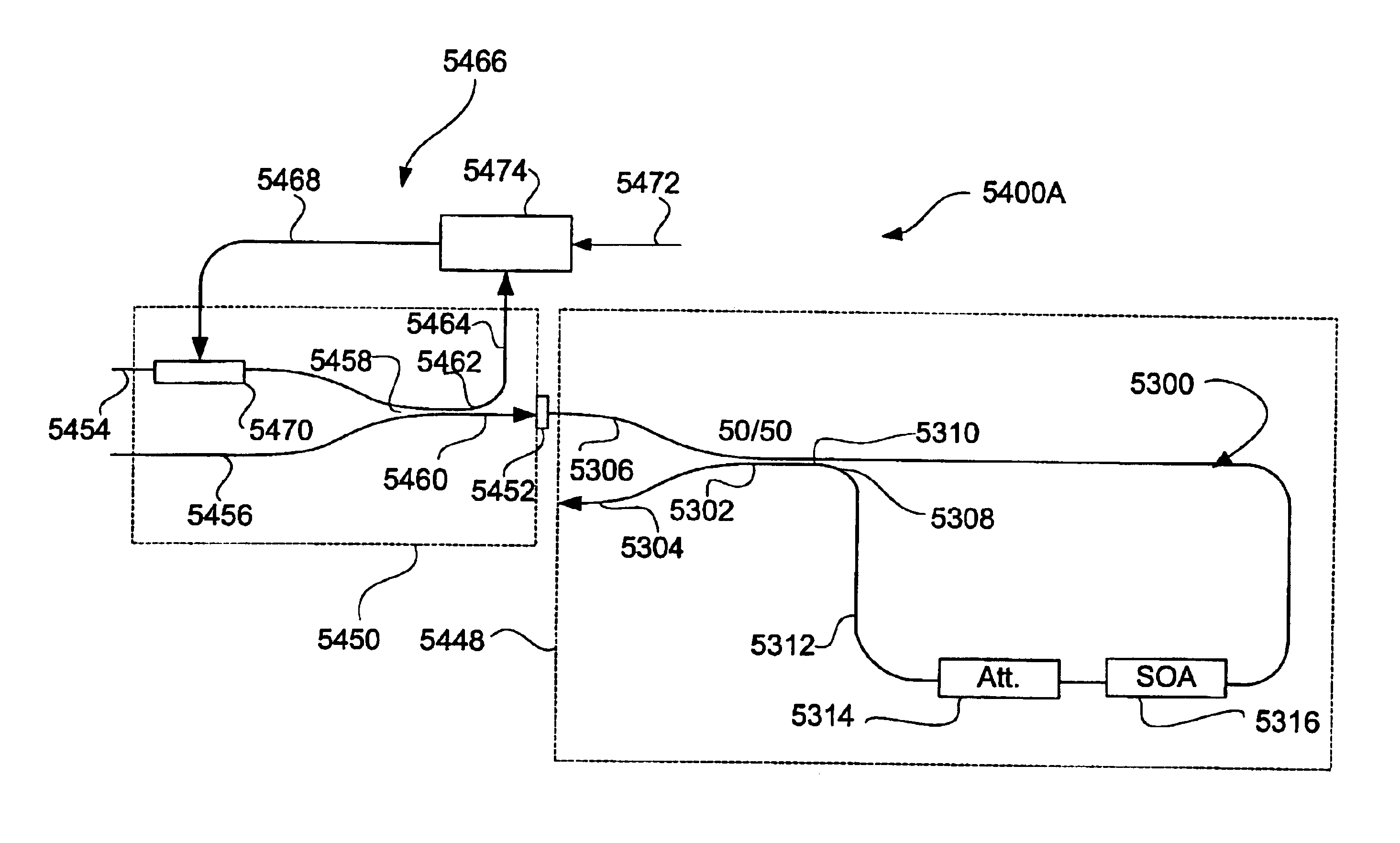
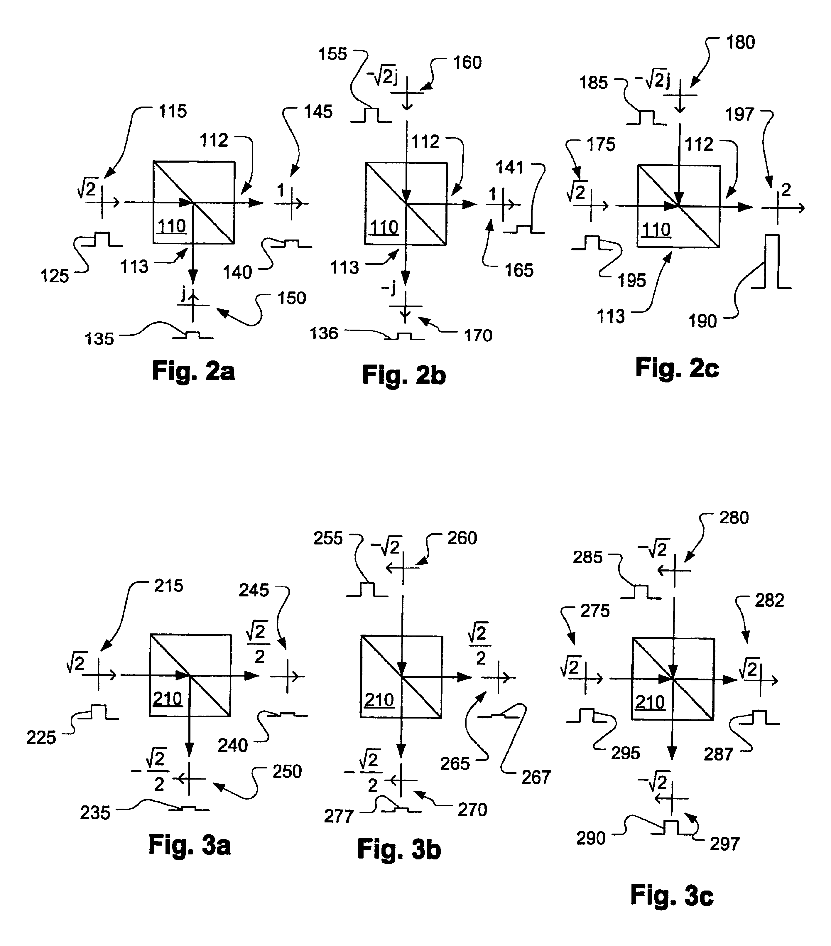
[0070]Some of the logic gates according to the present invention, which are discussed first, include summing gates that are combined with threshold devices. The summing gates include two inputs and at least two outputs in a configuration that one of the outputs is used as a coincidence output. The signals produced, by the summing gate at its coincidence output, are fed into the input of a threshold device. The threshold device produces an output signal only if it is fed, at its input, by a signal that its amplitude is above a certain threshold level. Each of the inputs of the summing gate may receive input signals A or B. When either of the inputs of the summing gate receives input signal A or B (a non-coincidence state), a low level signal that is under the threshold level of the threshold device is produced, by the summing gate, at the coincidence output. In this case, the threshold device receives, at its input, a signal that is below its threshold and thus no output signal is pr...


PUM


Abstract

An optical AND logic gate includes a summing gate having first and second inputs for receiving first and second optical signals, and a threshold device. The gate produces an output corresponding to the AND product of the first and second optical signals. In another version the AND gate includes first and second inputs for receiving first and second optical signals, and an optical loop for producing an output corresponding to the AND product of the first and second optical signals. In an alternative versions a NAND gate is provided by applying an optical logic NOT on an AND gate.

Description

CROSS-REFERENCE TO RELATED APPLICATIONS[0001]This application claims the benefit of U.S. Provisional Patent Application Ser. No. 60 / 461,796, filed Apr. 11, 2003, entitled “All Optical Logic Gates”, and is a continuation in part of U.S. patent application Ser. Nos. 10 / 404,077, pending, and 10 / 404,140 filed Apr. 2, 2003, now U.S. Pat. No. 6,795,626, entitled “Optical Threshold Devices and Methods”. The latter application claims the benefit of U.S. Provisional Patent Application Ser. No. 60 / 405,697, filed Aug. 22, 2002, entitled “Streaming signal control system for digital communications” now filed as four regular U.S. patent application Ser. Nos. 10 / 640,035, pending; 10 / 640,035, pending; 10 / 640,017, pending and 10 / 640,040, pending filed Aug. 14, 2003, entitled “All Optical Decoding Systems For Decoding Optical Encoded Data Symbols Across Multiple Decoding Layers”, “All Optical Decoding Systems For Optical Encoded Data Symbols”, “All Optical Cross Routing Using Decoding Systems For Opt...

Claims


Application Information

Patent Timeline
IPC IPC(8): G02B6/00G02F3/00G02B6/04G02B6/12G02B6/125G02B6/28G02B6/34G02F1/225G02F1/35H04J14/02H04J14/08
CPCG02B6/125G02B6/2861G02F1/225G02F1/3511H04J14/02G02B6/04H04J14/08G02B6/2804G02B2006/12107G02B2006/12142G02B2006/12145G02B2006/12147G02B2006/12164G02F1/3523G02B6/12009
Inventor SHAHAR, ARIEHALBERTHAL, ELDAN
Owner MAIN STREET VENTURES
Learn More