
Characterization of multiple section semiconductor lasers

a semiconductor laser and multiple section technology, applied in the direction of laser details, laser optical resonator construction, laser output parameters control, etc., can solve the problem of much lower power level, and achieve the effect of reducing the time for characterization of tslds

Inactive Publication Date: 2006-01-24
XLIGHT PHOTONICS
View PDF6 Cites 2 Cited by
  • Summary
  • Abstract
  • Description
  • Claims
  • Application Information

AI Technical Summary

Benefits of technology

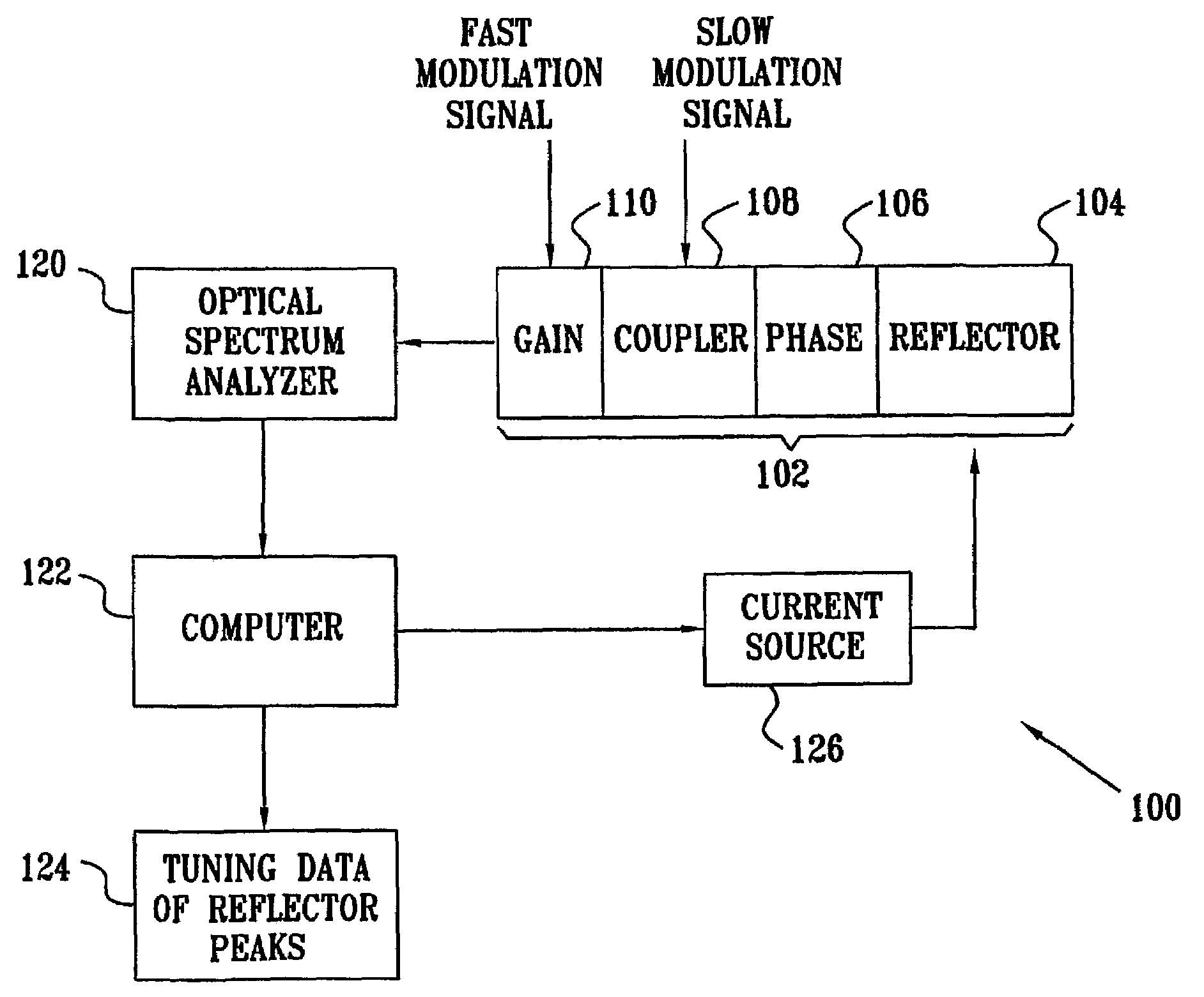
[0012]The present invention seeks to provide a new method that substantially reduces the time for characterization of TSLD's as compared to that of prior art methods. In this method the laser is stimulated in a way that discloses the optical properties and tuning current dependency of the individual sections of the laser, separately for each section, and independently of the other sections. This reduces the problem from a multi-dimensional problem, to a set of separate one dimensional problems which can be solved serially. Once this has been performed, each section of the laser can be tuned separately to the desired wavelength, independently of the other sections.
[0013]The method, according to a preferred embodiment of the present invention, is operative to maintain fairly constant lasing power level during a change in one of the tuning currents, without the need to adjust the other currents. This enables the monitoring of the change in wavelength associated with the tuning of that particular section alone, without dependence on the other sections. Unlike the situation existing in the prior art methods, according to the various embodiments of the present invention, the output of the laser can be observed continuously during the characterization process, without the need for continuous adjustments of the various section currents.
[0017]It is known that during turn-on time, or when the laser is modulated, i.e. the gain section is modulated, preferably by current modulation, the laser exhibits multimode operation. This is because of the time required for the main lasing mode to build up and dominate over the other modes. When the laser is modulated at a high enough rate, there is not enough time for this build-up to be completed. In this case the gain section acts as a quasi white light source, in accordance with the discrete Fabry Perot modes present, making it possible for a number of modes to arise without the need for phase adjustment using the phase current. These modes will be at wavelengths of high net gain in the laser cavity.
[0018]According to another preferred embodiment of the present invention, the application of modulation to the gain section makes it possible to view the spectral response of the laser, including the combined spectral structure of all the sections over a wide range. A change in the tuning current to one section shifts the total spectral response of the laser and also consequently the radiating modes, thus making it possible to determine the tuning characteristic of that section.
[0019]According to another preferred embodiment of the present invention, instead of modulating the gain in order to stimulate multi-mode operation, modulation can be applied to the phase section. As the phase current changes, the Fabry Perot modes shift in wavelength and effectively scan the spectrum, providing an opportunity for different wavelengths to radiate, provided the modes associated with those wavelengths have enough gain in the cavity. These wavelengths do not radiate simultaneously, as opposed to the previously described embodiment of the invention, where the gain section is modulated. However, by viewing the complete spectral output of the laser, integrated over a time significantly longer than the modulation period, it is possible to obtain a complete plot of the gain versus wavelength. Thus, by changing the tuning current to one of the sections, it is possible to monitor the change in the spectral response of the laser, and to obtain the tuning characterization of that section, independently of the other sections.
[0020]When the laser is stimulated to operate at many wavelengths, according to either of the above-preferred embodiments using gain modulation or modulation of the phase section, the gain in the cavity depends on the product of the transmission of all the wavelength selective sections in the laser. According to another preferred method of the present invention, in order to isolate the response of one section only, an additional modulation signal is applied to other sections, thus effectively canceling the spectral effect of the modulated sections on the laser output. The response of those sections is spread over the complete spectrum of the laser output. The total time-integrated response of those sections is thus uniform. The only element of the laser that maintains a wavelength selective function is that of the section that is not modulated. Consequently, that section alone will essentially determine the wavelengths and relative powers that the laser emits. Changing the tuning current to that section enables the monitoring of the change in the spectral response of the laser, and thus the determination of the tuning characterization of that section.

Problems solved by technology

However in CW operation the preferably excited main lasing mode suppresses any other gain peaks, causing them to have much lower power levels.

Method used


Image

  • Characterization of multiple section semiconductor lasers
  • Characterization of multiple section semiconductor lasers
  • Characterization of multiple section semiconductor lasers

Examples


Embodiment Construction

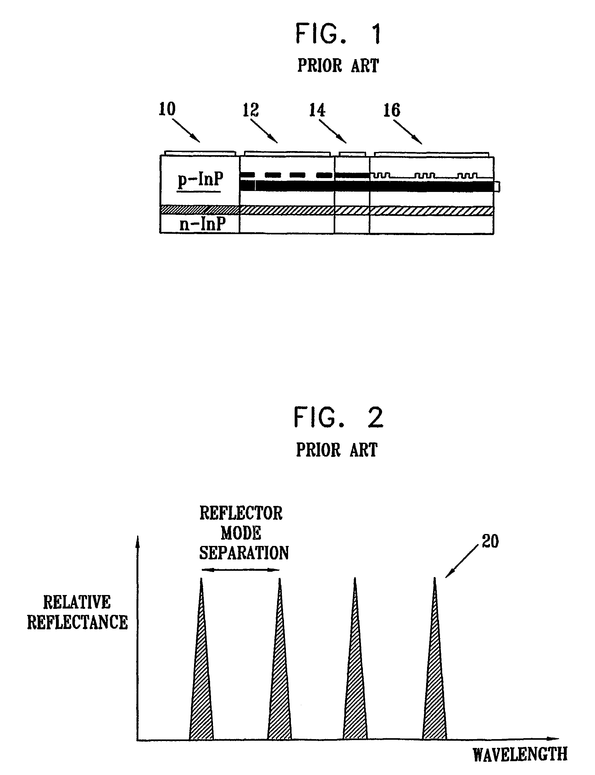
[0067]Reference is now made to FIG. 1, which illustrates schematically the structure of a commonly used TSLD, showing the constituent sections operative in determining the lasing wavelength of the device. The TSLD shown is known as a Grating Coupler Sampling Reflector laser, or a GCSR laser. The GCSR laser is used in this specification to illustrate the methods of the various preferred embodiments of the present invention, though it is to be understood that the methods described are applicable and operable also with other TSLD's.

[0068]The GCSR laser has four sections, a Gain section 10, a Sampled Reflector 16, a Coupler 12, and the Phase section 14. These sections function in the following manner:

[0069]In the gain section 10, the generation and amplification of photons takes place. The current to this section is the pump current for the laser, and affects the tuning mechanism in a similar manner to the phase section.

[0070]A Sampled Reflector 16, is placed at one end of the resonator...


PUM


Abstract

A method for characterizing tunable semiconductor laser diodes in which the laser is stimulated in a way that discloses the optical properties and tuning current dependency of the individual sections of the laser, separately for each section, and independently of the other sections. A section of the laser is current modulated in order to excite a continuum of modes related to the spectral response of other sections. This process is observed by viewing the overall spectral response at an integration time significantly longer than the modulation time. The spectral positions of the modes and their dependence on the tuning current, are used to determine the tuning characteristic of that particular section. This method substantially reduces the time required for characterization of such lasers in comparison with prior art methods.

Description

FIELD OF THE INVENTION[0001]The present invention relates to the field of tunable semiconductor laser diodes, especially methods of characterizing the currents required to tune the laser to a desired wavelength.BACKGROUND OF THE INVENTION[0002]Tunable semiconductor laser diodes (TSLD's) are key components in the implementation of present and future optical communication systems. The first TSLD's used temperature control tuning, i.e. a temperature change generated in the TSLD caused a change in its physical dimensions, thus changing its wavelength. This method of tuning the laser is relatively slow. The tuning time is in the order of milliseconds or more, making it too slow for applications where fast wavelength switching is required. Furthermore, the repeatability, accuracy and tuning range are limited and unsuitable for advanced applications such as dense dynamic WDM systems, and optical switches and routers.[0003]A laser can radiate at wavelengths that have a round trip phase chan...

Claims


Application Information

Patent Timeline
IPC IPC(8): H01S3/10H01S3/00H01S5/00H01S5/06H01S5/0625H01S5/10H01S5/12
CPCH01S5/06255H01S5/0014H01S5/0617H01S5/06251H01S5/1209H01S5/06256H01S5/1035H01S5/06253
Inventor BUIMOVICH, EFRAIMRUBIN, SHMUELSADOT, DAN
Owner XLIGHT PHOTONICS
Learn More