Detector for electromagnetic radiation assisted by majority current
a technology of electromagnetic radiation and detector, applied in the field of electromagnetic radiation detection, can solve the problem that the proportion of minority carriers that reach effectively the target accumulation zone is far from optimal, and achieve the effect of reducing the capacitance of the detection region, fast and sensitive detector, and reducing the capacitan
- Summary
- Abstract
- Description
- Claims
- Application Information
AI Technical Summary
Benefits of technology
Problems solved by technology
Method used
Image
Examples
first embodiment
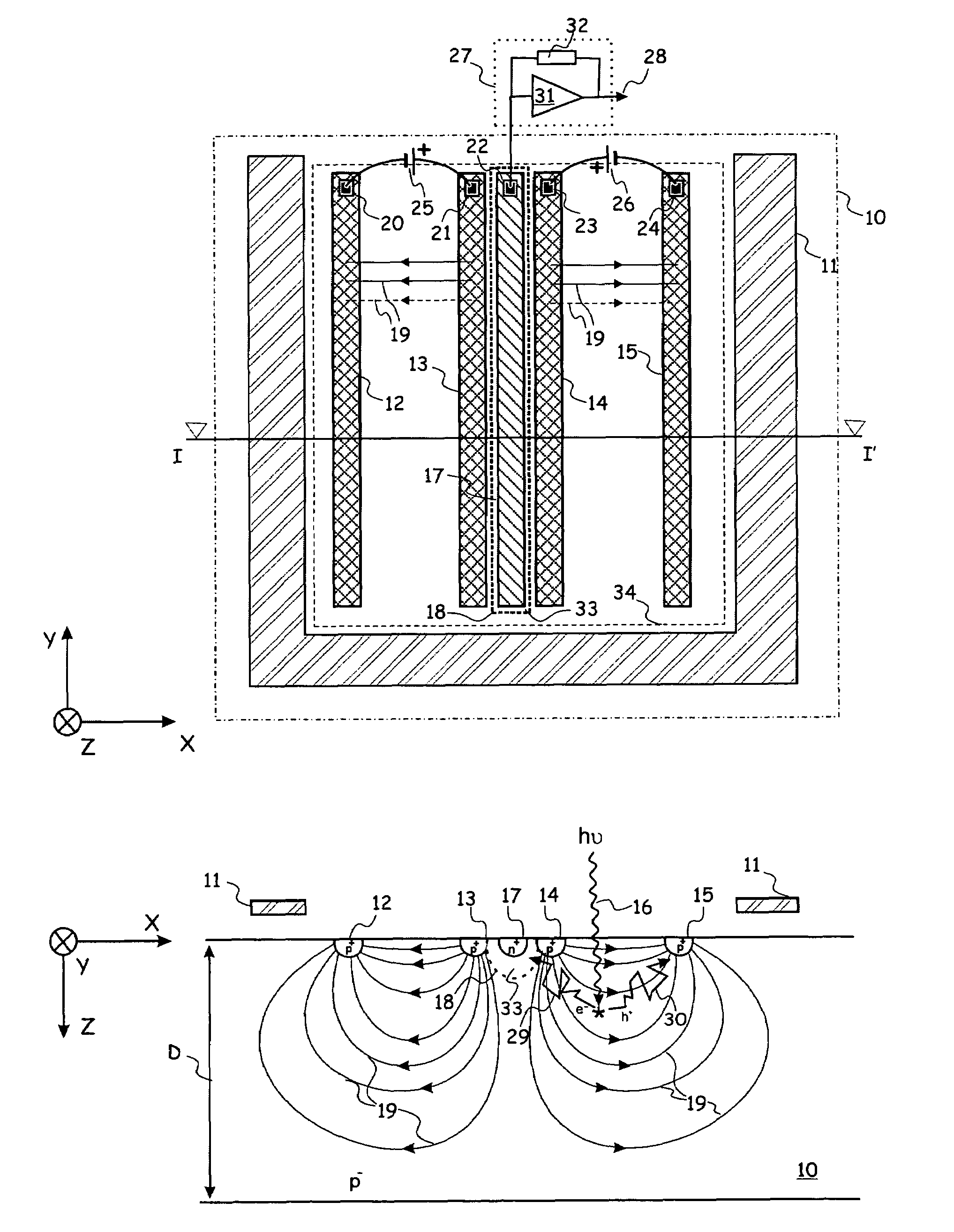
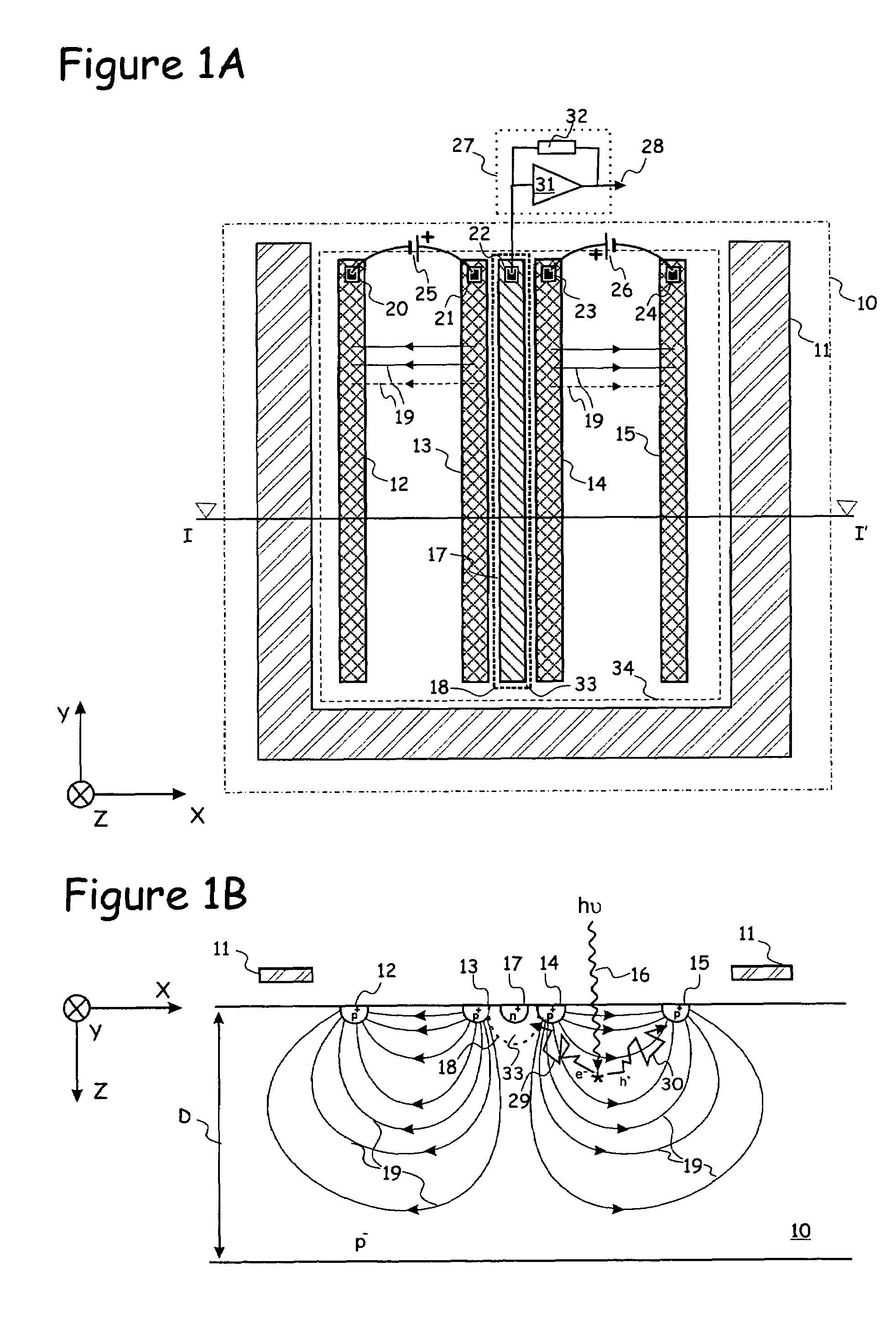
[0039]FIG. 1A shows a top view of a photo-detector according to the present invention. Sources 25 and 26 inject current at contacts 21 and 23 respectively, and drain current at contacts 20 and 24 respectively. Contacts 20, 21, 23 and 24 connect through ohmic-conduction to highly doped regions having a first conductivity type, e.g. p+-regions 12, 13, 14 and 15 respectively. In a resistive, lightly doped substrate having the first conductivity type, e.g. p− substrate 10, a majority carrier current, in the case of a substrate being a p− substrate, a hole current 19 will flow from region 13 to region 12, and from region 14 to region 15. Line I–I′ in FIG. 1A shows where the cross-section is made for FIG. 1B. In FIG. 1B, the majority hole current 19 is shown by solid lines whereby the direction of the hole current 19 is indicated by arrows. In the substrate 10, where the doping is typically considered to be constant, the majority current 19 is associated with an electrical field, in the d...
second embodiment
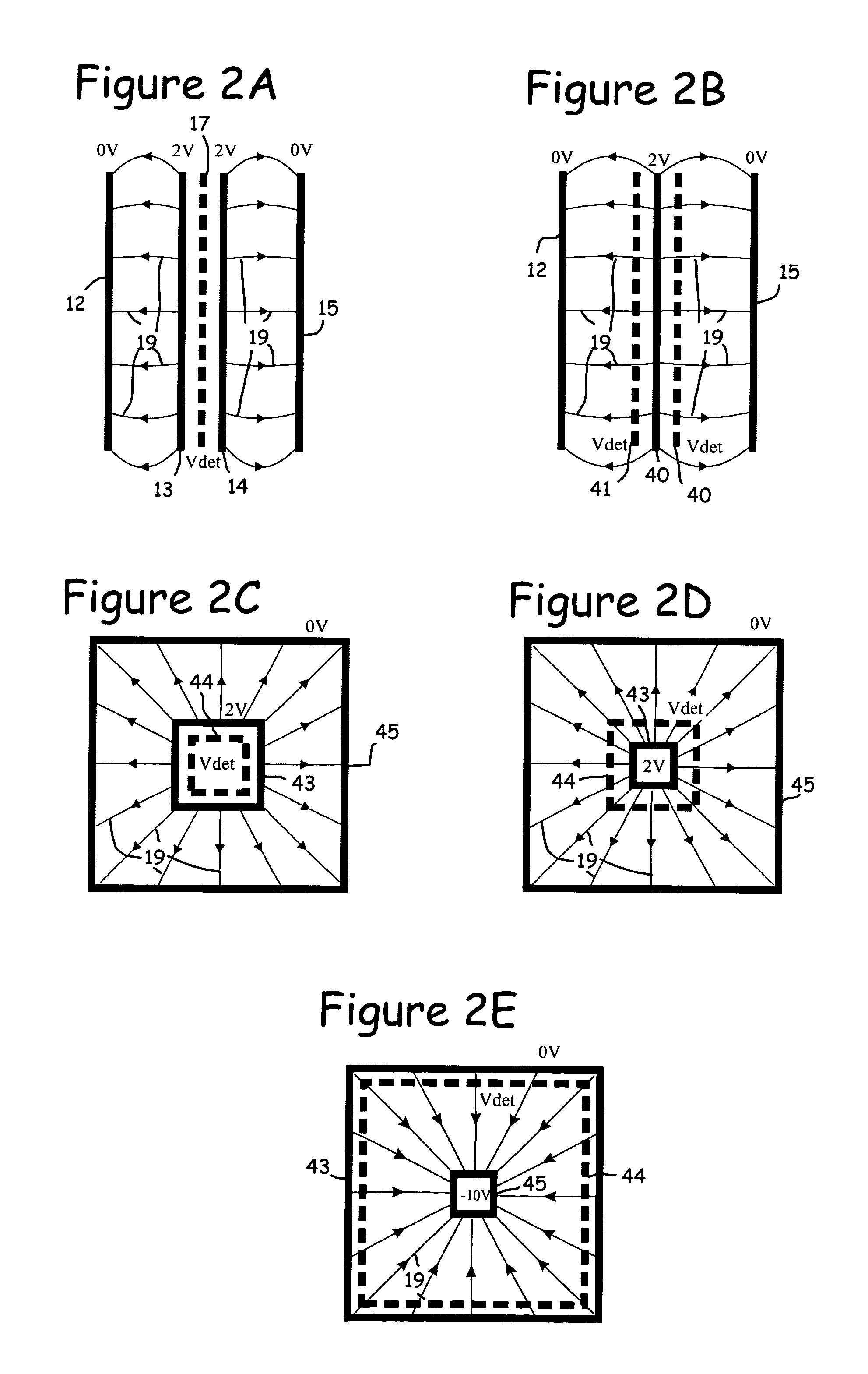
[0050]FIG. 2B shows a detector according to the present invention. It comprises only one source region 40 for injection of the majority current 19, with at each side of it a detector finger 41, 42. In the embodiment shown, the source region 40 is located in the middle of the device. The detector fingers 41, 42 should be connected in parallel. This set-up enhances the speed of the diffusion part of the detecting process, but it also doubles the detector capacitance, since the number of detector fingers 41, 42 is doubled.
[0051]FIGS. 2C and 2D illustrate detectors of a rectangular type.
[0052]Especially the embodiment of FIG. 2C is considered a preferred arrangement or best mode example, since in this embodiment the detector capacitance becomes extremely low. Instead of using a detector finger 17, which for example has a dimension of 40 μm×3 μm, there is a detecting pn-junction 44 with an area that can be as small as of the order of only 3 μm×3 μm, whilst the sensitive light input area ...
third embodiment
[0053]The detector of the third embodiment illustrated in FIG. 2D has in the centre its current source region 43, surrounded by a detecting pn-junction 44. Here the detector capacitance is somewhat higher, since the area of the detecting pn-junction 44 is somewhat larger, but it remains low. This set-up enhances the speed of the diffusion part of the detecting process, since the current source region 43 is surrounded by the detecting pn-junction 44.
PUM
 Abstract
Description
Claims
Application Information
 - R&D
- Intellectual Property
- Life Sciences
- Materials
- Tech Scout
- Unparalleled Data Quality
- Higher Quality Content
- 60% Fewer Hallucinations
Browse by: Latest US Patents, China's latest patents, Technical Efficacy Thesaurus, Application Domain, Technology Topic, Popular Technical Reports.
© 2025 PatSnap. All rights reserved.Legal|Privacy policy|Modern Slavery Act Transparency Statement|Sitemap|About US| Contact US: help@patsnap.com


