
Ultrasonic sealing apparatus

a sealing apparatus and ultrasonic technology, applied in the direction of transportation and packaging, packaging, other domestic objects, etc., can solve the problems of uneven vibration, new sealing failure, damage to laminated packaging materials, etc., and achieve the effect of uniform application of sufficient pressing for

Inactive Publication Date: 2006-01-17
SHIKOKU KAKOOKI CO LTD
View PDF33 Cites 27 Cited by
  • Summary
  • Abstract
  • Description
  • Claims
  • Application Information

AI Technical Summary

Benefits of technology

[0009]An object of the invention is to provide an ultrasonic sealing apparatus capable of preventing the sealing failure owing to the tunnel (through passage) occasionally occurring in the step portions in the vicinity of both end portions of the longitudinally sealed portion when the tubular laminated packaging material is transversely ultrasonically sealed with a fluid and the like.
[0011]Accordingly, differing from a conventional solving method in which a shape for improving sealability is given to the sealing face of a heating source side, the ridge was provided on a pressing face of an opposing jaw for pressing a laminated packing material in cooperation with the sealing face of the horn. It was found that this was somewhat effective for preventing the tunnel or through passage from occurring, but a new problem surfaced in that the laminated packaging material was injured by the ridge. Therefore, means for increasing the pressing force applied to a pressing face without providing a protruded portion such as the ridge were studied. As a result, it was found that if a center portion was formed in the longitudinal direction of a pressing face of the opposing jaw, and against which a longitudinally sealed portion of the three-ply portion was butted to achieve a pressing face narrower than both end portions, a necessary pressing force could be evenly applied to the longitudinally sealed portion of the three-ply portion without injuring the laminated packaging material, and thereby the invention was completed.
[0026]It is also possible to form, in the pressing face formed narrowly, a recess having an arc shape and the likes in section along a direction perpendicular to the longitudinal direction of the pressing face. By providing such a recess, even if the tubular laminated packaging material is rotated about a center axis of the tube as the axis of rotation and so a longitudinally sealed portion of the three-ply portion somewhat deviates from a regular position, it follows that step portions in the vicinity of both end portions of the longitudinally sealed portion butt against the recessed pressing face formed narrowly, so that it is possible to evenly apply a sufficient pressing force required for an excellent seal to the longitudinally sealed portion of the three-ply portion. As such a recess, the arc shape in section is desirable. However, any shape may suffice so long as it can apply the sufficient pressing force required for the excellent seal to step portions in the vicinity of the both end portions of the longitudinally sealed portion of the three-ply portion even in case where the longitudinally sealed portion of the three-ply portion somewhat deviates from the regular position.
[0027]Further, the present invention relates to an ultrasonic sealing apparatus characterized in that an elongated pressing face pressing the laminated packaging material in corporation with a sealing face of a horn is provided in the opposing jaw working portion of the opposing jaw, and a recess having are arc shape and the like in section is formed in a center portion in a longitudinal direction of the pressing face of the opposing jaw along a direction perpendicular to the longitudinal direction of the pressing face. By providing such a recess, even if the tubular laminated packaging material is rotated about a center axles of the tube as the axis of rotation and so a longitudinally sealed portion of the three-ply portion somewhat deviates from a regular position, it follows that step portions in the vicinity of both and portions of the longitudinally sealed portion butt against the recessed action face formed by the recess, so that it is possible to evenly apply a sufficient pressing force required for an excellent seal to the longitudinally sealed portion of the three-ply portion. As such a recess, the arc shape in section is desirable. However, any shape may suffice so long as it can apply the sufficient pressing force required for the excellent seal to step portions in the vicinity of both end portions of the longitudinally sealed portion even in case where the longitudinally sealed portion of the three-ply portion somewhat deviates from the regular position.

Problems solved by technology

The study found that it became difficult to maintain an evenness in vibration owing to the ridge provided on the sealing face of the horn and, for this reason, a new sealing failure occurred.
It was found that this was somewhat effective for preventing the tunnel or through passage from occurring, but a new problem surfaced in that the laminated packaging material was injured by the ridge.
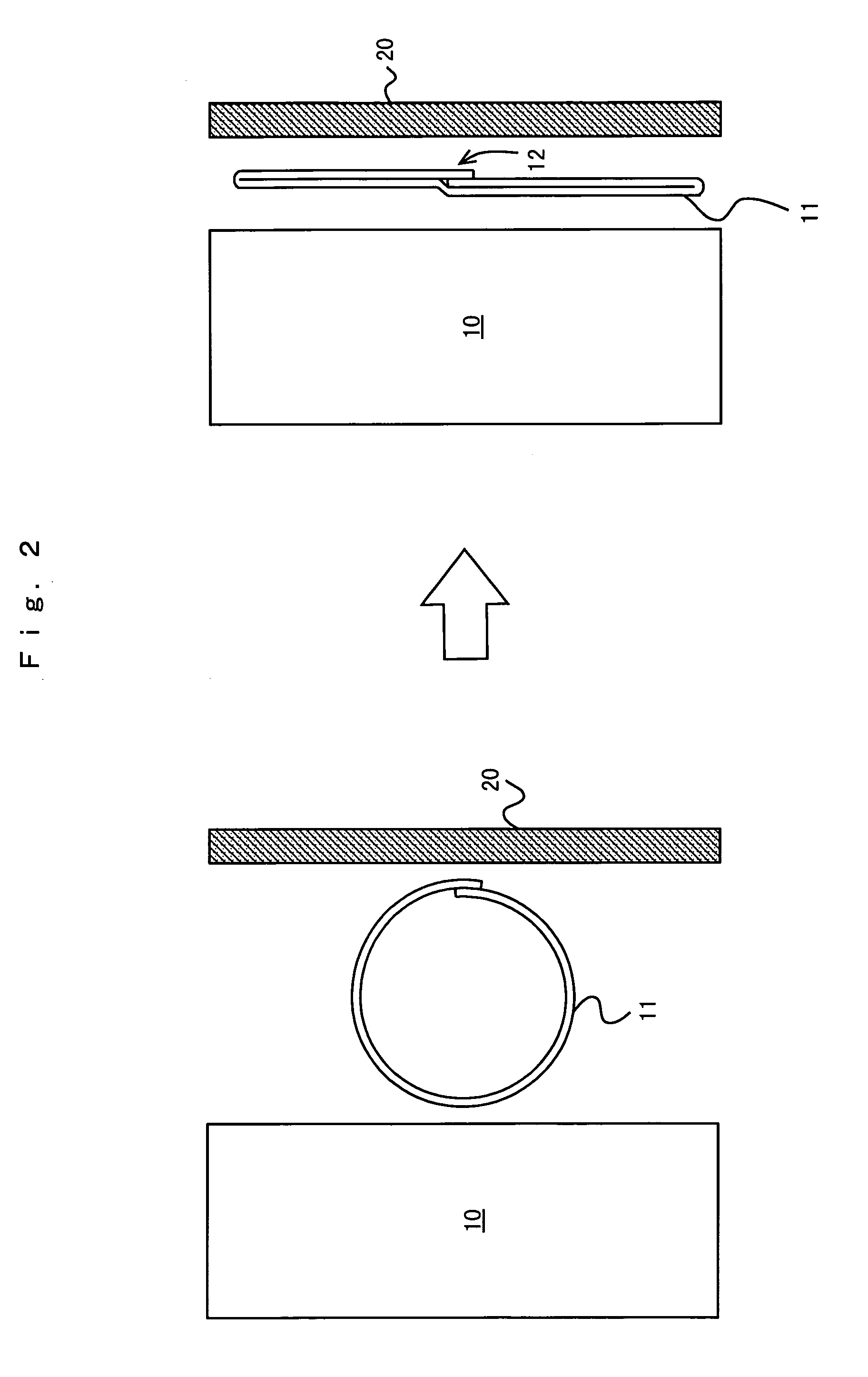
During a process of the above study, It was found that there was such a case that the tubular laminated packaging material was rotated about a center axis of the tube and so a longitudinally sealed portion of the three-ply portion somewhat deviated from a regular position, i.e., a relief center position of the opposing jaw shown in FIG. 2, and that, as a result, a sufficient pressing force was not applied to either of the step portions in the vicinity of both end portions of the longitudinally sealed portion.

Method used


Image

  • Ultrasonic sealing apparatus
  • Ultrasonic sealing apparatus
  • Ultrasonic sealing apparatus

Examples


Embodiment Construction

[0048]Hereunder, embodiments and the like of the present invention are described in detail referring to FIGS. 4–24, but a technical scope of the invention is not limited to the embodiments. Incidentally, in FIGS. 4–24, 20 denotes an opposing jaw, 21 denotes an opposing jaw body, 22 denotes an opposing jaw working portion, 23 denotes both end portions in a longitudinal direction of a pressing face, 24 denotes a narrow pressing face of a center portion in a longitudinal direction of the pressing face, 25 denotes a recess having an arc shape in section, 26 denotes a recess corresponding to a shape of a longitudinally sealed portion, and 27 denotes recesses of various shapes, respectively.

[0049]In FIG. 4 and FIG. 5, there is shown a main portion of the opposing jaw 20. The center portion formed in a longitudinal direction of the pressing face in the opposing jaw working portion 22 that is provided on one face of the opposing jaw body 21 of the opposing jaw 20 is narrower than the both e...


PUM

PropertyMeasurementUnit
Lengthaaaaaaaaaa
Shapeaaaaaaaaaa
Widthaaaaaaaaaa

Abstract

An ultrasonic sealing apparatus prevents a sealing failure by preventing a tunnel (through passage) to form in the step portions in the vicinity of both end portions of longitudinally sealed portions, when the tubular laminated packaging material is transversely ultrasonically sealed. An ultrasonic sealing apparatus, in which a laminated packaging material containing a thermoplastic resin layer and a paper layer is formed into a tubular form and the tubular laminated packaging material is transversely ultrasonic sealed, includes a horn having an elongated and flat sealing face and an opposing jaw having an elongated pressing face which presses the laminated packaging material in cooperation with the sealing face of the horn, wherein the center portion in longitudinal direction of the pressing face of the opposing jaw is narrower than both end portions of the pressing face. Further, at a center portion in longitudinal direction of a pressing face of the opposing jaw, a recess having an arc shape, etc. in section is formed along a direction perpendicular to the longitudinal direction of the pressing face.

Description

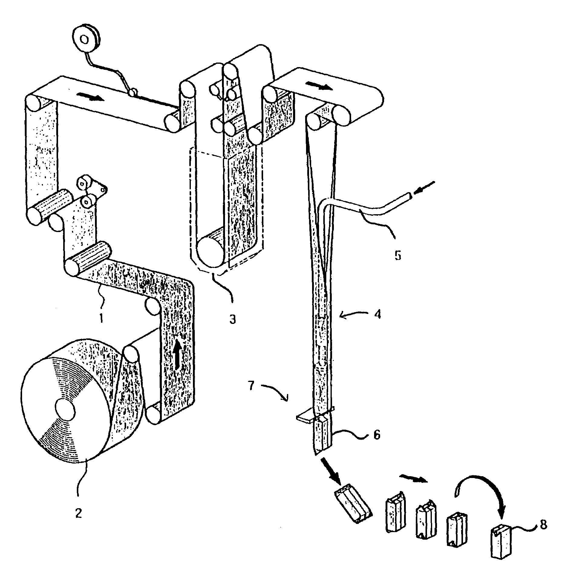
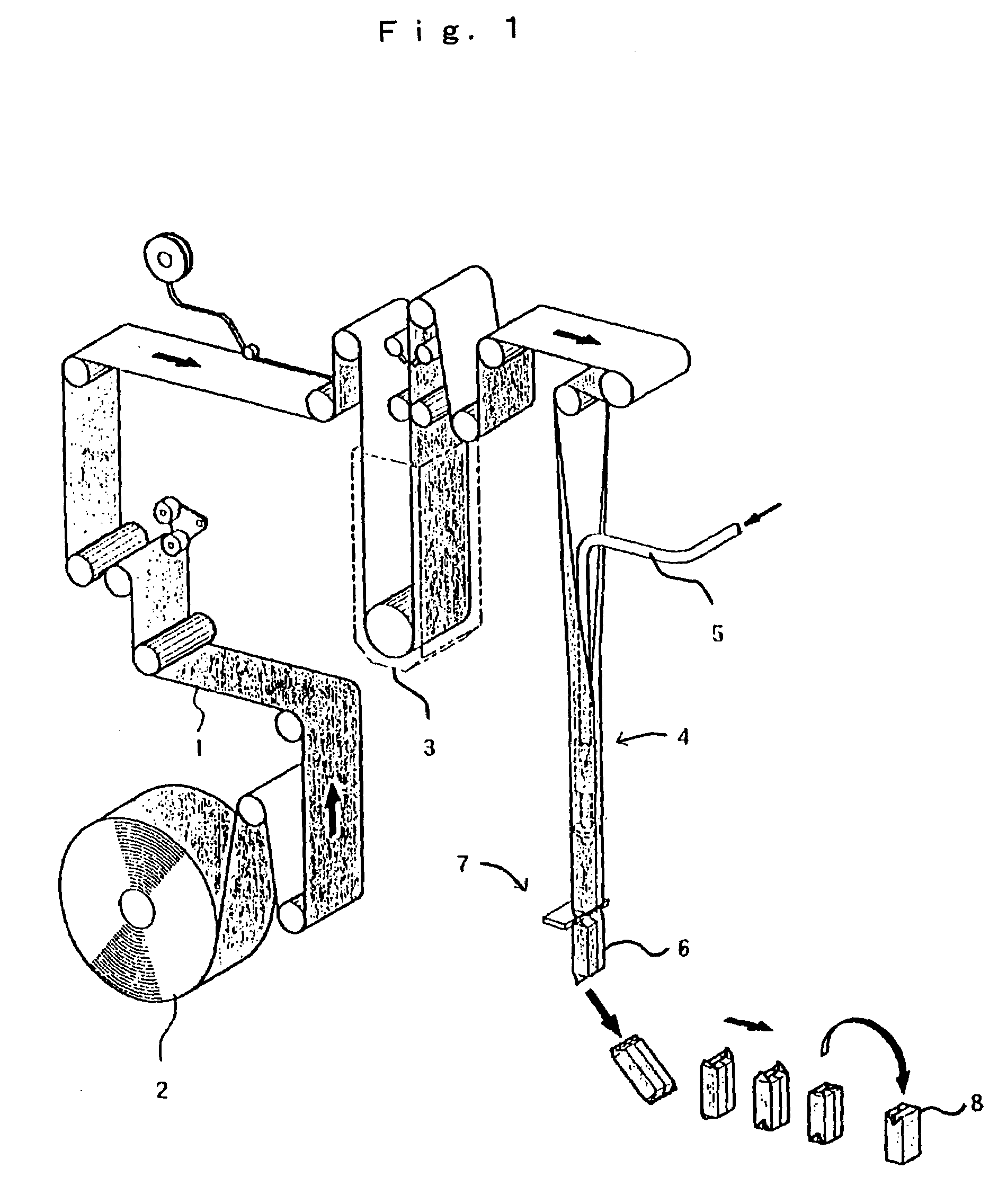
CROSS REFERENCE TO RELATED APPLICATIONS[0001]Priority is claimed with respect to Japanese Application No. 11 / 191040 filed Jul. 5, 1999, in the Japanese Patent Office, the disclosure of which is incorporated herein by reference.BACKGROUND OF THE INVENTION[0002]1. Field of the Invention[0003]The present invention relates to an ultrasonic sealing apparatus for transversely sealing a tubular laminated packaging material filled with a content such as a liquid beverage, and more particularly to an ultrasonic sealing apparatus provided with an opposing jaw having a specified shape for improving sealability by controlling molten thermoplastic resin flow.[0004]2. Description of the Related Art[0005]Hitherto, as a packaging machine in which a packaging material web for a rectangular parallelepiped packaging container filled with juice, etc. is used by being sterilized, there has been known a filling and packaging machine shown in FIG. 1. In summary, the filling and packaging machine comprises...

Claims


Application Information

Patent Timeline
IPC IPC(8): B65B51/10B65B51/00B29C53/42B29C53/54B29C65/00B29C65/08B29C65/50B29C65/74B29C65/78B65B51/22B65B51/30
CPCB29C66/8145B29C65/08B29C65/7894B29C66/1122B29C66/346B29C66/4312B29C66/81423B29C66/81433B29C66/849B65B51/225B65B51/30B29C66/81427B29C66/81431B29C53/54B29C53/42B29C65/5042B29C65/7451B29K2711/123Y10S53/02B29C66/83411B29C66/4322B29C66/8322B29C66/73921B29L2031/7166B29C66/72321B29C66/72328B29C66/72341
Inventor KUME, SATOSHISHINOHARA, MITSUHIKOISEKI, TAKESHIUEDA, MICHIO
Owner SHIKOKU KAKOOKI CO LTD
Learn More