
Patient positioning device

a positioning device and positioning device technology, applied in the field of patient positioning devices, can solve the problems of difficult tightening, obesity, elderly or pregnant patients, and difficulty in this treatment method, and achieve the effect of convenient transportation

Inactive Publication Date: 2006-01-17
GES CO
View PDF24 Cites 45 Cited by
  • Summary
  • Abstract
  • Description
  • Claims
  • Application Information

AI Technical Summary

Benefits of technology

[0010]The patient positioning device may also have a pad, which is preferably a thigh support pad, that is coupled to the leg support. The thigh support pad can be moved laterally with the leg support so that it can be moved behind a patient's thighs. This pad provides comfort to a patient's legs as it provides a stationary force absorbing fulcrum for the moment arm if traction is to be employed. Preferably, the leg cushion is coupled to the pad, so that the leg cushion moves laterally with the rails and the pad. As described above and below, the tracks and rails permit the thigh support pad and the leg support to be moved to a position that fits a particular patient's anatomy.

Problems solved by technology

Difficulties arise with this treatment method in the case of obese, elderly or pregnant patients.
With obese patients, for instance, the harness belt is frequently difficult to tighten sufficiently to capture the pelvis, which results in the force from the traction head being distributed through the soft tissues throughout the pelvis.
This results in (1) discomfort to the patient; (2) slippage of the belts; and (3) uncertainty as to the actual spinal treatment force.

Method used


Image

  • Patient positioning device
  • Patient positioning device
  • Patient positioning device

Examples


Embodiment Construction

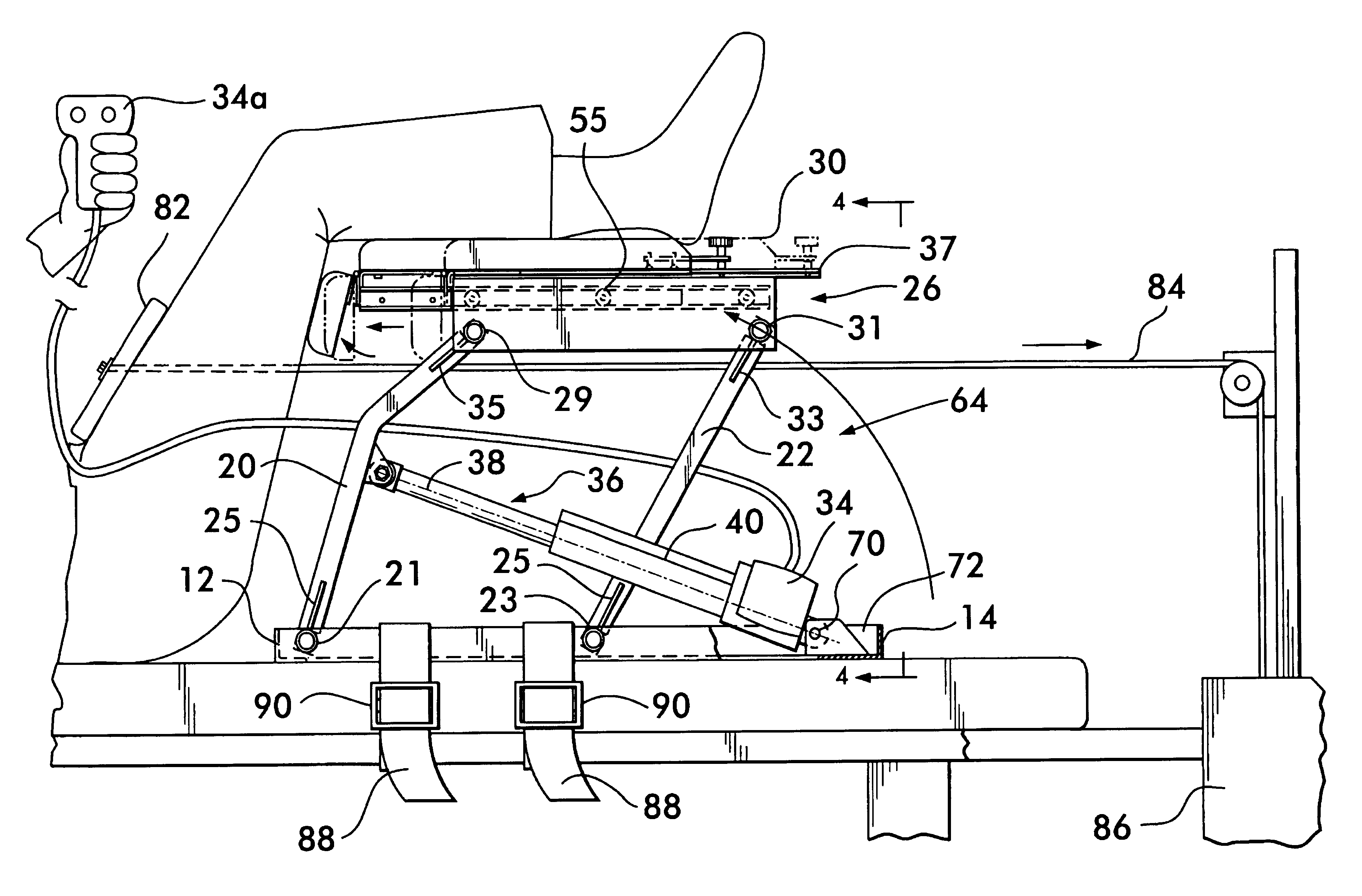
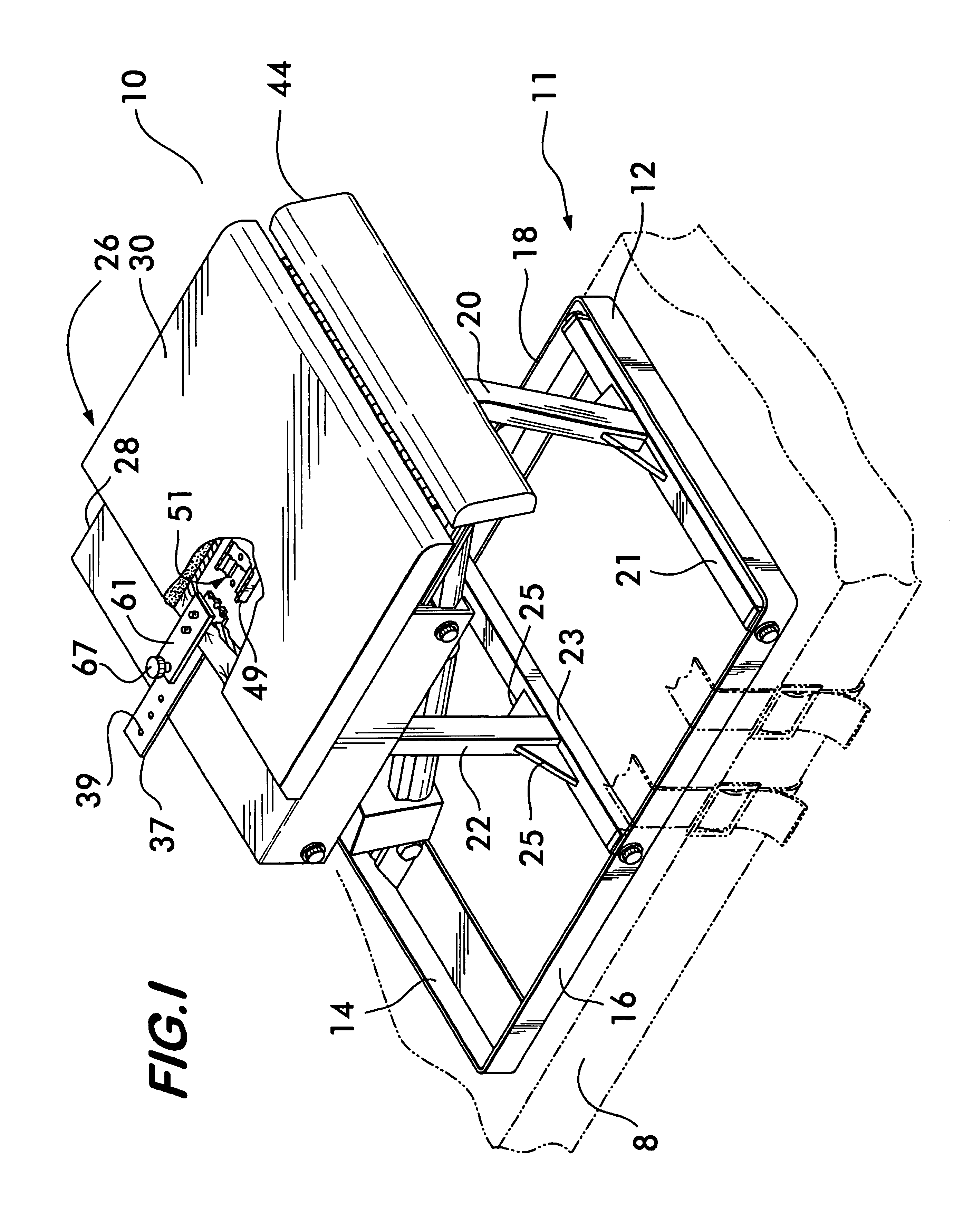
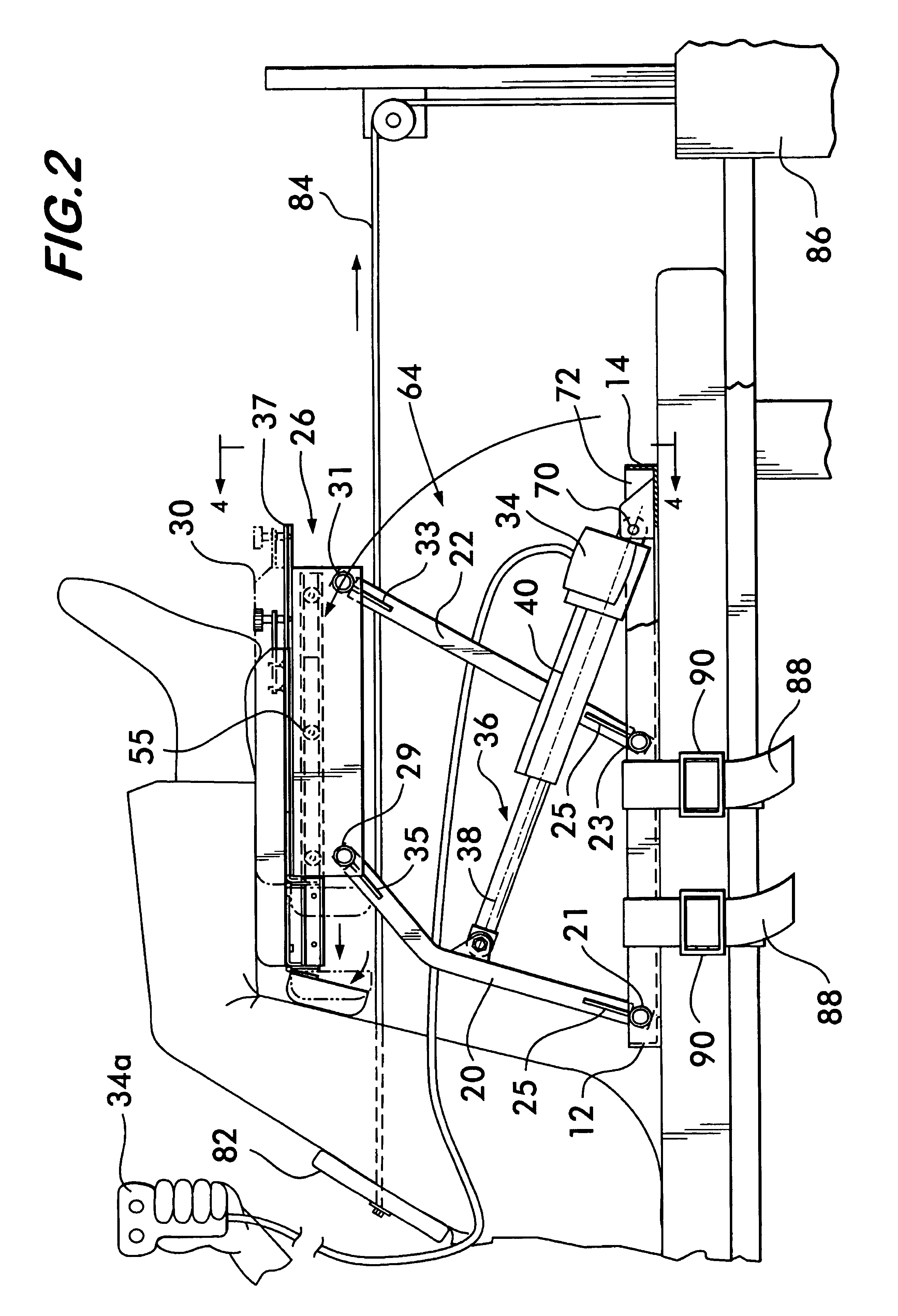
[0021]The patient positioning device 10 is portable and can be easily transported and adapted to a patient's treatment table 8 or any other suitable surface. The treatment table may, but need not be, a Triton Table available from the Chattanooga Group, Inc. The surface may be inclined. As described below, the patient positioning device 10 can be rotated from a lowered position to an elevated position. A perspective of an embodiment of the patient positioning device 10, that is partially cut away at the top, is shown in FIG. 1. FIGS. 2 and 4 illustrate the patient positioning device 10 in an elevated position, and FIG. 3 depicts the patient positioning device 10 in a lowered position. (FIG. 2 depicts the device 10 in an elevated position, but not fully elevated, and FIG. 4 depicts the device 10 in a fully elevated position so that the details of the device are better understood.)

[0022]As shown in FIG. 1, the patient positioning device 10 includes a bottom frame 11. The bottom frame 1...


PUM


Abstract

The patient positioning device of this invention relates to an apparatus used to assist a patient into a supine position and additionally through which traction is applied to the spine, such as physical therapy and chiropractic treatment. The patient positioning device is preferably a stand alone portable device that can be readily transported and adapted to almost any horizontal surface, such as a treatment table. A primary application of the leg support of this invention is in raising and supporting a patient's lower legs during before, during, and after traction is applied to a patient. The device includes a lower support frame, vertical supports, and a leg support coupled to a top frame. The patient positioning device may also have a motor which powers the leg support to rotate from a lowered position, in which a patient's lower legs rest on the leg support, to an elevated position in which a patient's lower legs are elevated. Once in the elevated position, traction can be applied to the lower back preferably with a cable and a board that is placed across the front of a patient's thighs.

Description

FIELD OF THE INVENTION[0001]The invention relates to an apparatus used to position a patient into the supine position. This invention also relates to a system that positions a patient and applies traction to the spine, such as physical therapy and chiropractic treatment.BACKGROUND OF THE INVENTION[0002]The practice of applying traction to the spine of a patient for therapeutic purposes is commonly prescribed by physicians, physical therapists and chiropractors. When professional judgment calls for a patient to be placed in a supine position, a harness is normally attached to the patient by encircling the lower abdomen with a harness that consists of a belt which must be attached by straps to a traction head. The Saunders Group, Incorporated of Chaska, Minn. sells harnesses of this type including its harness model # 46210. The belt portion which encircles the abdomen must be cinched tightly enough to capture the pelvis of the patient and thus transfer the traction force from the trac...

Claims


Application Information

Patent Timeline
IPC IPC(8): A47C20/02A61H1/02
CPCA61H1/0292A61H1/0218A61H1/0255A61H2203/045A61H2201/1642
Inventor MURPHY, STEPHEN P.MURPHY, EDWARD T.MURPHY, GEORGE W.
Owner GES CO
Learn More