
Proximity detector and radiography system

Inactive Publication Date: 2006-01-10
GE MEDICAL SYST GLOBAL TECH CO LLC
View PDF22 Cites 137 Cited by
  • Summary
  • Abstract
  • Description
  • Claims
  • Application Information

AI Technical Summary

Benefits of technology

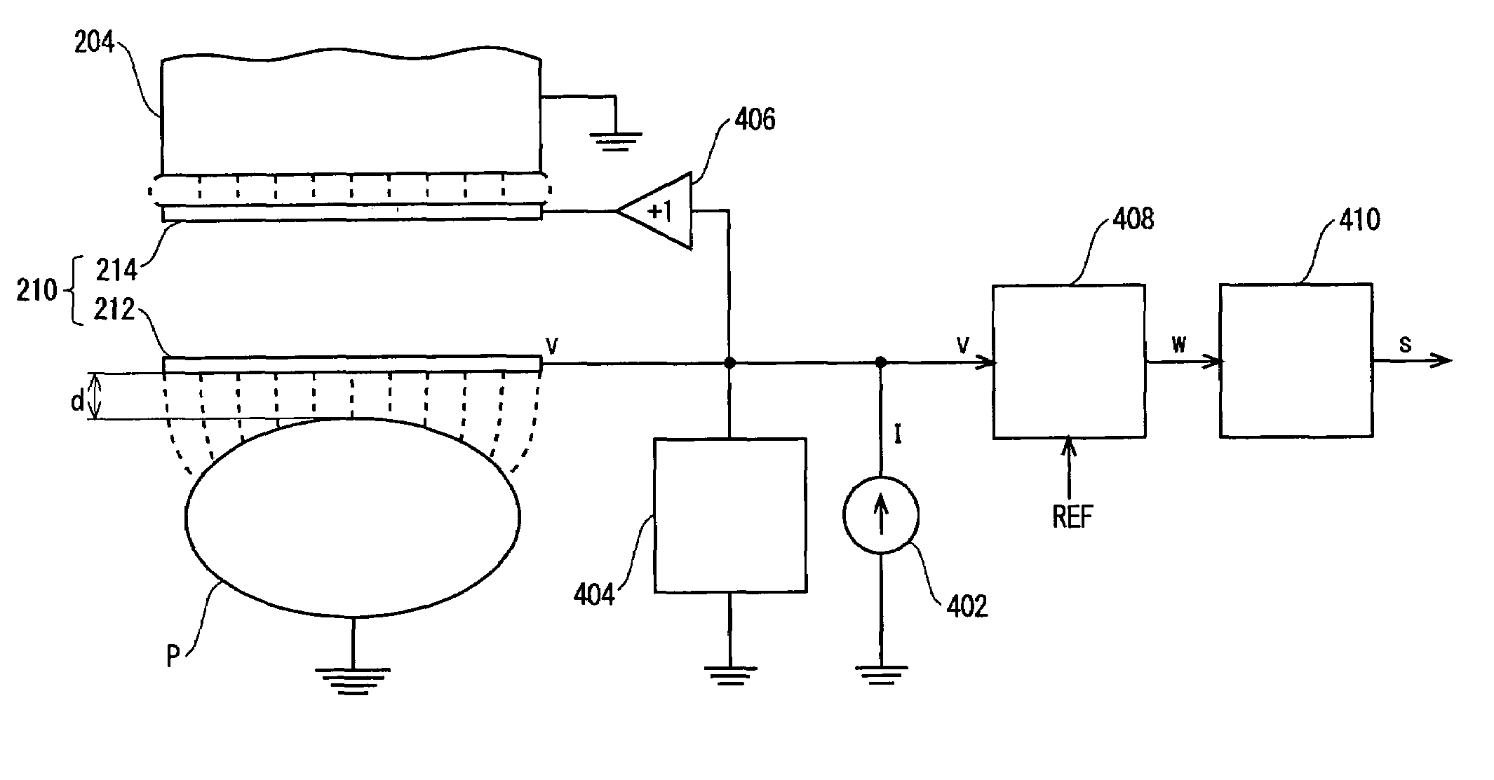
[0014]Certain embodiments of the present invention provide a proximity detector having a simple configuration and an imaging system including the proximity detector. In a certain embodiment, the imaging system includes a movable member capable of approaching a subject and a proximity detector. The proximity detector indicates an approach of the movable member within a certain distance of the subject based on an electric field. The proximity detector includes an electrode mounted on the movable member, a current feeding device for feeding a current to an electrostatic capacitor formed between the electrode and a ground, and a discharging device for releasing charge from the electrostatic capacitor at intervals of certain cycle.
[0020]In an embodiment, since the single electrode is adopted, the configuration of a sensor is simplified. Moreover, a constant current is fed to the electrostatic capacitor formed between the electrode and a ground. Charge is released from the electrostatic capacitor at intervals of a certain cycle. A potential at the electrode relative to a ground is binary coded based on a threshold. An output signal of the binary-coding device is smoothed in order to produce a detection signal. This results in the simplified configuration of an electric circuit.
[0021]In an embodiment, the electrode has two conductive layers electrically isolated from each other. The constant current is fed to an outer layer of the conductive layers, and a voltage same as one applied to the outer layer is applied to an inner layer. In this case, sensitivity to be attained in proximity detection improves.
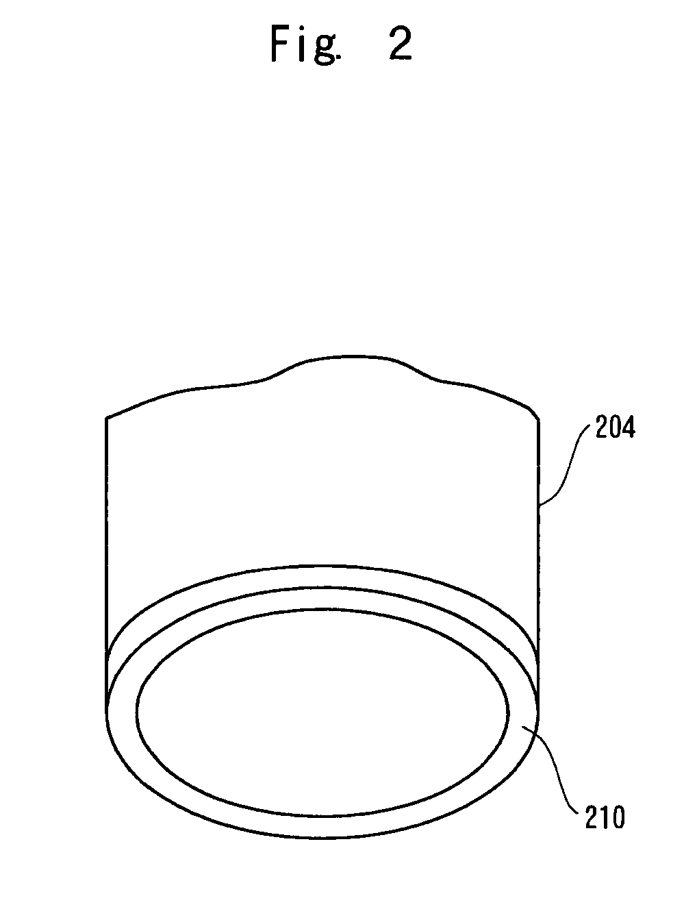
[0022]In an embodiment, the electrode is formed along a perimeter of a receiving surface of the x-ray receiving device, so that the adverse effect on incident x-rays may be minimized. In an embodiment, the electrode is formed over a periphery of the x-ray receiving device and a perimeter of a receiving surface thereof. In this case, while the adverse effect on incident x-rays may be minimized, the area of the electrode may be increased.
[0023]In an embodiment, the supporting device supports the x-ray irradiating device and x-ray receiving device at respective ends of a C-arm. In this case, diverse accesses to a subject are permitted. In an embodiment, the x-ray receiving device includes image intensifier so that the sensitivity to incident x-rays may be improved.
[0024]Certain embodiments of the present invention provide a proximity detector having a simple configuration and an imaging system including the proximity detector.

Problems solved by technology

Motorized motion of any of the axes of a mobile C-arm system poses possible risks to the patient and to the imaging system and other equipment.
A possibility of collision exists whether the C-arm is moved through automated trajectory tracking or through direct user input from a user interface device.
The scanning circuitry increases overhead on sensing circuitry for the imaging system.
Current proximity sensors are limited by the complexity of electronic circuitry.
Complex, additional electrical circuitry impacts the cost, maintenance, and performance, for example, of the imaging system.
Current sensor systems are also limited by distances between sensors and imaging system components.
That is, operating constraints limit the distance between a proximity sensor and an image intensifier, for example.
Additionally, current sensor systems are limited by the use of an electromagnetic field for proximity detection.
Furthermore, capacitive proximity sensing has not been used with a mobile C-arm apparatus.

Method used


Image

  • Proximity detector and radiography system
  • Proximity detector and radiography system
  • Proximity detector and radiography system

Examples


Embodiment Construction

[0031]For the purposes of illustration only, the following detailed description references a certain embodiment of an x-ray radiography system using a C-arm. It is understood that the present invention may be used with other imaging systems, such as a mobile C-arm system or other imaging modality.

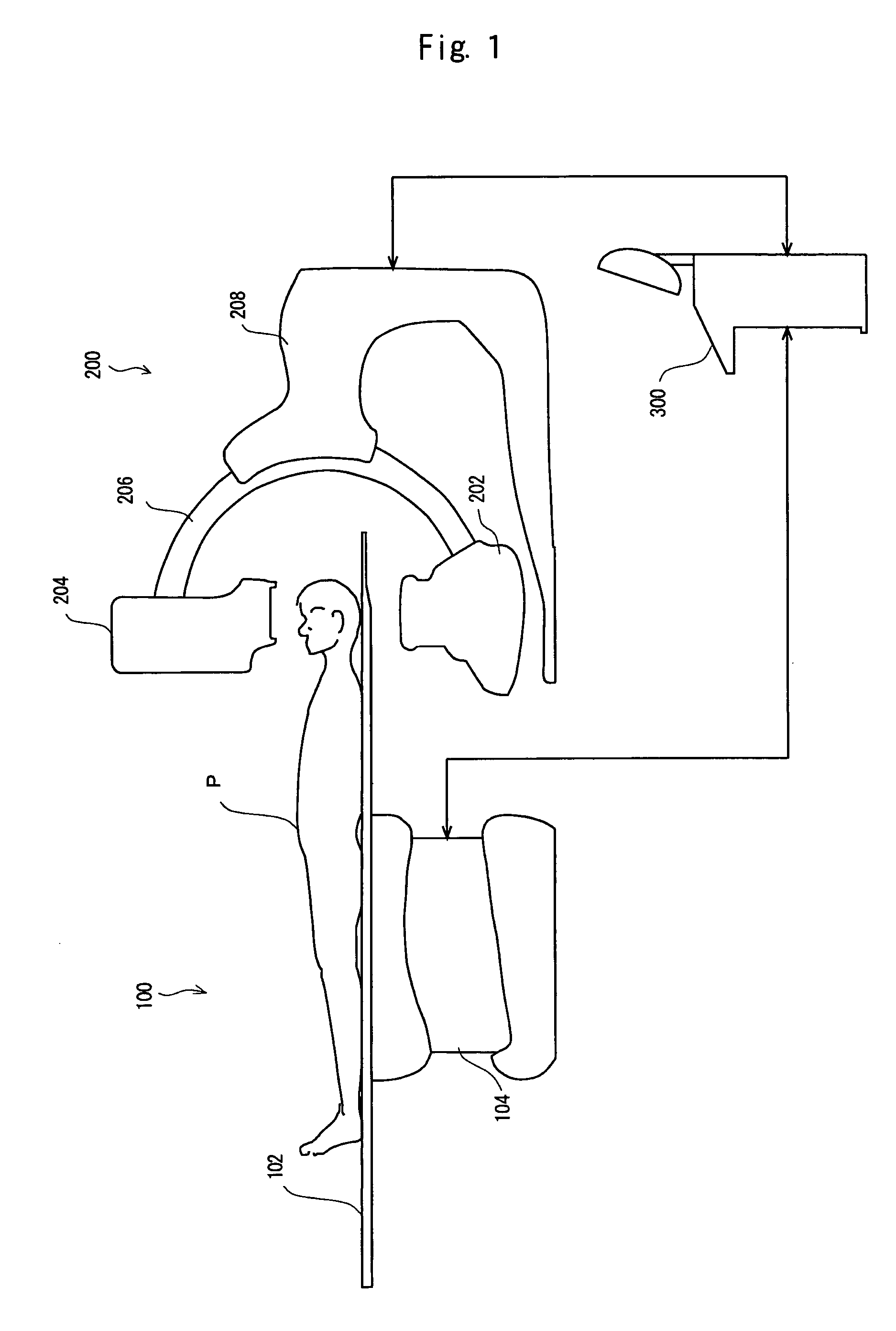
[0032]FIG. 1 illustrates a configuration of a radiography system used in accordance with an embodiment of the present invention. The radiography system includes a table 100, a gantry 200, and an operator console 300.

[0033]The table 100 has a tabletop 102. A subject P of radiography is positioned on the tabletop 102. The tabletop 102 is supported by a base 104. An advancing / withdrawing mechanism, a raising / lowering mechanism, and a tilting mechanism are incorporated in the base 104. The mechanisms advance, withdraw, raise, lower, and / or tilt the tabletop 102.

[0034]The gantry 200 includes an arc-shaped C-arm 206 for supporting an x-ray irradiator 202 and an x-ray receiver 204. The irradiator ...


PUM


Abstract

Certain embodiments of the present invention provide a proximity detector having a simple configuration and an imaging system including the proximity detector. In an embodiment, a proximity detector mainly comprises: a single electrode mounted on a subject-side end of a movable member; a current feeding device for feeding a constant current to an electrostatic capacitor formed between the electrode and a ground; a discharging device for releasing charge from the electrostatic capacitor at intervals of a certain cycle; a binary-coding device for binary-coding the potential at the electrode relative to a ground based on a threshold; and a smoothing device for smoothing an output signal of the binary-coding device.

Description

RELATED APPLICATIONS[0001]The present application claims priority under 35 U.S.C. 119 to Japanese Patent Application No. JP2002-379671, filed on Dec. 27, 2002, to Giridharan Shanmugavel and Hariharan Krishnaswami.FEDERALLY SPONSORED RESEARCH OR DEVELOPMENT[0002][Not Applicable]MICROFICHE / COPYRIGHT REFERENCE[0003][Not Applicable]BACKGROUND OF THE INVENTION[0004]The present invention relates to a proximity detector and a radiography system, and more particularly, to a proximity detector for detecting the proximity of a movable unit to a subject using proximity sensing and to a radiography system including the proximity detector.[0005]Imaging systems, such as x-ray radiography systems, are typically positioned close to a patient or subject to be imaged in order to provide desired imaging information. One type of radiation imager is a mobile C-arm system. In the medical field, the mobile C-arm system may be used for general surgery, orthopedic procedures, pain management procedures, vas...

Claims


Application Information

Patent Timeline
IPC IPC(8): H05G1/54A61B6/10
CPCA61B6/102
Inventor SHANMUGAVEL, GIRIDHARANKRISHNASWAMI, HARIHARAN
Owner GE MEDICAL SYST GLOBAL TECH CO LLC
Learn More