Control unit for vehicle brake system

a control unit and brake system technology, applied in the direction of braking systems, magnets, magnetic bodies, etc., can solve the problems of insufficient contact between the flux return casing and the valve seat, and the magnetic field to collaps

Inactive Publication Date: 2006-01-10
KELSEY HAYES CO
View PDF15 Cites 32 Cited by
  • Summary
  • Abstract
  • Description
  • Claims
  • Application Information

AI Technical Summary

Benefits of technology

[0013]The present invention contemplates a coil assembly that comprises a coil wound upon a bobbin. A pair of terminals is supported by the bobbin. The coil has a pair of lead wires, each of which is connected to one of the terminals. Each terminal is adapted to be coupled to an electronic control unit. The coil is enclosed at least in part by a flux return casing. At least one resilient member is arranged and configured to urge the bobbin and the casing axially downward.
[0014]The present invention also contemplates an electronic control unit that includes a housing adapted to be mounted upon a hydraulic valve body. A circuit substrate is mounted within the housing and a coil spacer is mounted upon the circuit substrate. The coil spacer includes at least one coil support ring having a resilient member extending in a radial direction from the edge of the ring into the center of the ring. A solenoid coil and flux casing assembly is mounted upon the coil spacer ring with the coil flexing the resilient member such that the resilient member urges the flux casing away from the coil spacer and toward the hydraulic valve body. In the preferred embodiment, the coil spacer also includes an electrical connector for at least one pressure sensor and an electrical connector for a pump motor.
[0015]The present invention further contemplates a method for assembling an electronic control unit that includes providing at least one solenoid coil and mounting the solenoid coil upon a coil spacer. The coil spacer is mounted upon a circuit substrate to form an assembly and the assembly is inserted into a housing. As a further step, the housing is mounted upon a hydraulic valve body to form a hydraulic control unit.

Problems solved by technology

An interruption in the current causes the magnetic field to collapse.
A problem exists with positioning the coil assemblies relative to respective valves due to manufacturing tolerances.
In addition, an inability to control the position of the flux return casings relative to their respective valve seats may result in insufficient contact between the flux return casings and the valve seats.

Method used


Image

  • Control unit for vehicle brake system
  • Control unit for vehicle brake system
  • Control unit for vehicle brake system

Examples


Embodiment Construction

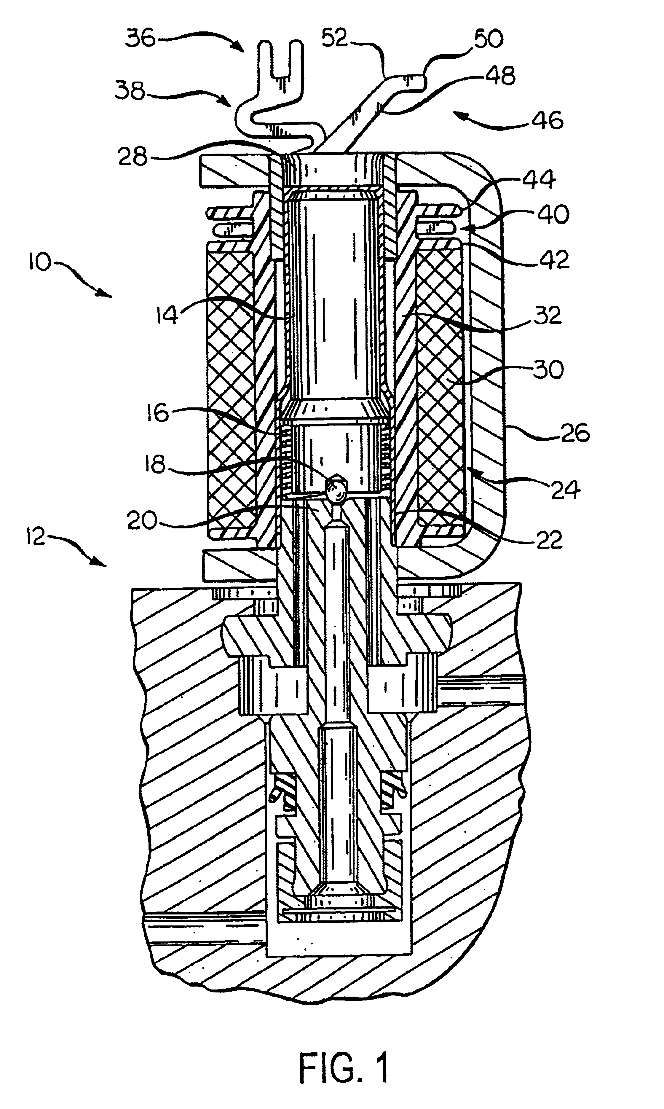
[0034]Referring now to FIG. 1, there is shown a sectional view of a solenoid valve 10 mounted upon a valve body 12. The valve 10 includes an axially shiftable armature 14, which is biased in an upward direction by a biasing element, such as the spring 16 shown. The spring 16 maintains a valve ball 18 in a normally opened position. Alternatively, a biasing element may be provided to maintain the valve ball 18 in a normally opened position. The valve ball 18 is adapted to cooperate with a valve seat member 20, which is provided in the valve body 12. The armature 14 is adapted to slide within a valve sleeve 22.

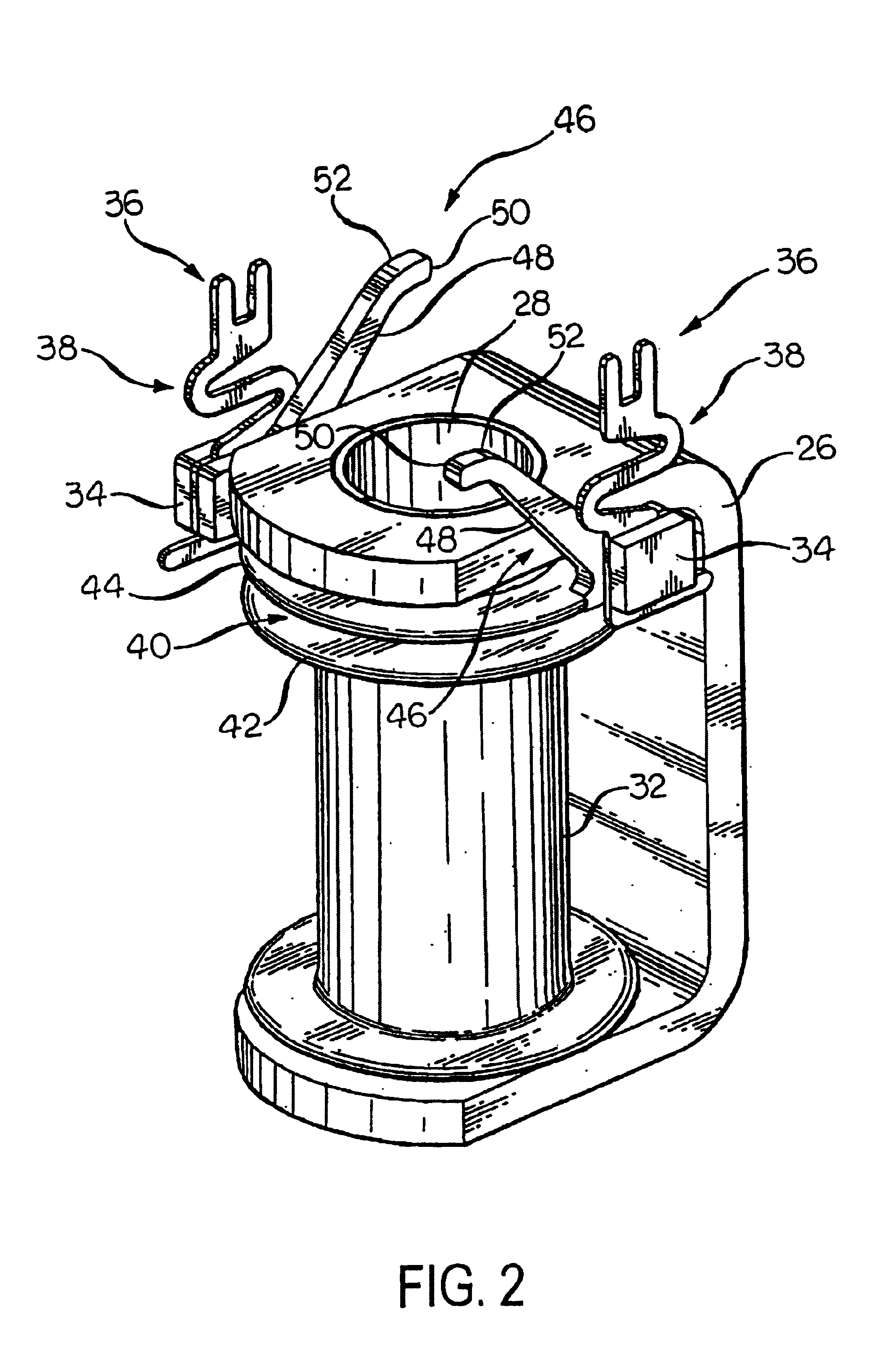
[0035]A coil assembly is carried by the valve sleeve 22. The coil assembly includes a solenoid coil 24. The coil 24 may be comprised of a coil winding 30 formed from multiple turns of an insulated magnet wire having a round cross-section, such as # 28½ magnet wire. The coil wire is preferably a helical coil wound upon a bobbin 32. The bobbin 32 is formed of a non-conductive mater...


PUM

PropertyMeasurementUnit
angleaaaaaaaaaa
angleaaaaaaaaaa
resilientaaaaaaaaaa

Abstract

A control unit having a circuit substrate mounted within a housing that is adapted to be mounted upon a hydraulic valve body with a coil spacer mounted upon said substrate. The coil spacer including at least one coil support ring having resilient member extending in a radial direction from the edge of the ring into the center of the ring. The control unit also including a solenoid coil and flux casing assembly mounted upon the coil spacer ring with the solenoid coil and flux casing assembly flexing the resilient member such that the resilient member urges flux casing away from the coil spacer.

Description

BACKGROUND OF THE INVENTION[0001]This invention relates in general to a solenoid coil assembly included in a vehicle anti-lock brake system and more particularly to a solenoid coil assembly that provides compensation for manufacturing tolerances.[0002]An anti-lock brake system (ABS) is often included as standard equipment on new vehicles. When actuated, the ABS is operative to control the operation of some or all of the vehicle wheel brakes. A typical ABS includes a plurality of normally open and normally closed solenoid valves which are mounted within a control valve body and connected to the vehicle hydraulic brake system. Usually, a separate hydraulic source, such as a motor driven pump, is included in the ABS for reapplying hydraulic pressure to the controlled wheel brakes during an ABS braking cycle. The pump is typically included within the control valve body while the pump motor is mounted upon the exterior of the control valve body.[0003]An ABS further includes an Electronic...

Claims


Application Information

Patent Timeline
Patent Type & Authority Patents(United States)
IPC IPC(8): B60T8/36H01F5/02H01F5/04H01F5/06H01F7/126H01F7/127H01F27/29
CPCB60T8/363B60T8/3675H01F5/04H01F7/126H01F27/29H01F5/02H01F2007/062H01F7/127H01F5/06
Inventor PARKER, DION S.HUGHES, TIMOTHY E.LEWIN, DOUGLASREA, PAOLOCOLLINS, DAVID E.
Owner KELSEY HAYES CO
Why Eureka
Try Eureka