
Method and arrangement for controlling an internal combustion engine

a technology of internal combustion engine and control method, which is applied in the direction of machines/engines, liquid fuel feeders, mechanical apparatuses, etc., can solve problems such as noise disturbance, and achieve the effect of avoiding unnecessary nois

Inactive Publication Date: 2006-01-10
ROBERT BOSCH GMBH
View PDF14 Cites 27 Cited by
  • Summary
  • Abstract
  • Description
  • Claims
  • Application Information

AI Technical Summary

Benefits of technology

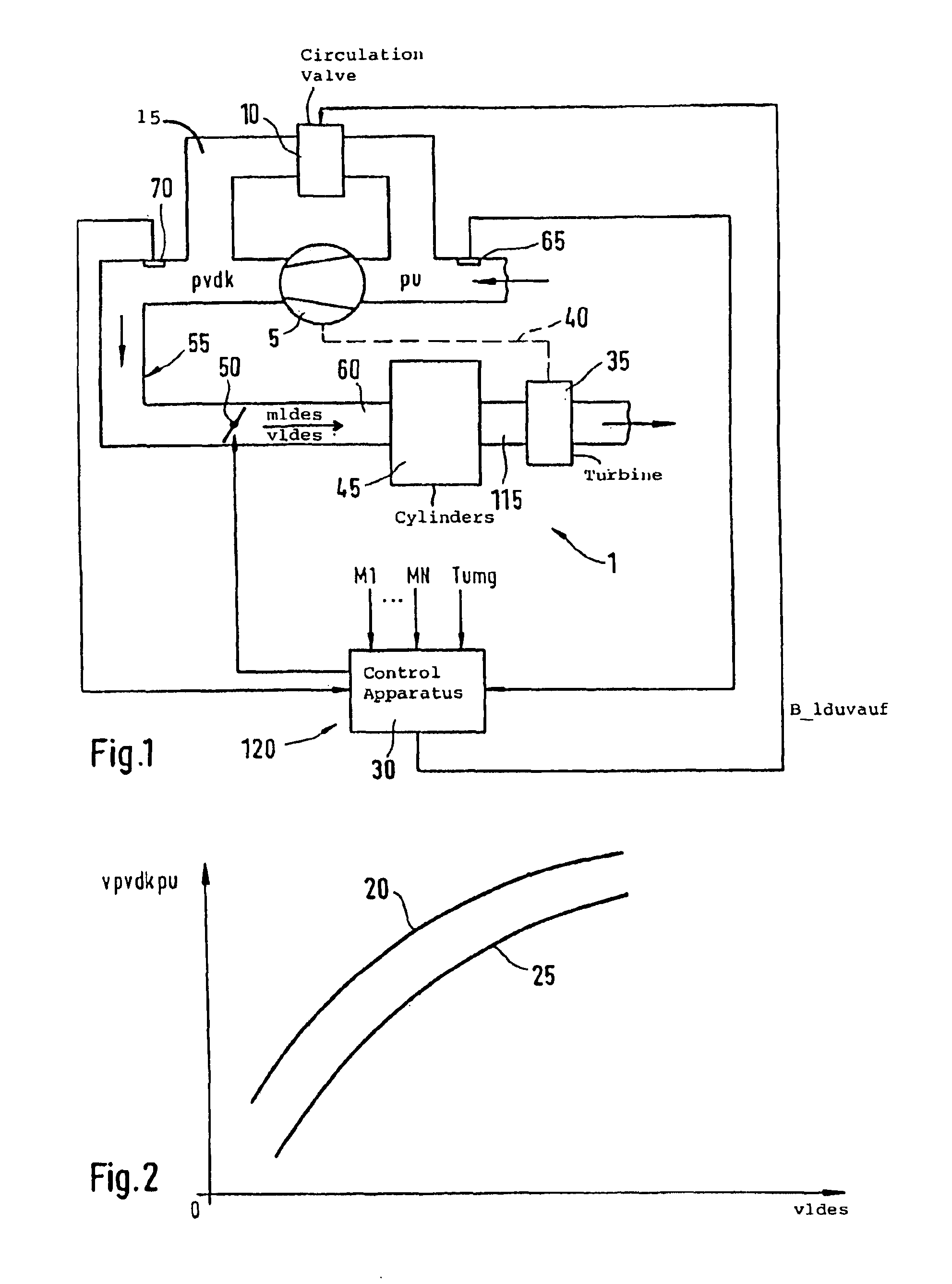
[0002]The method and arrangement of the invention for controlling an internal combustion engine afford the advantage with respect to the above that a valve of an air path, which bypasses the compressor, is controlled in dependence upon at least a pregiven characteristic line of a compressor characteristic field. In this way, and for a suitable input of this characteristic line, it can be ensured that the valve is opened only when really necessary.
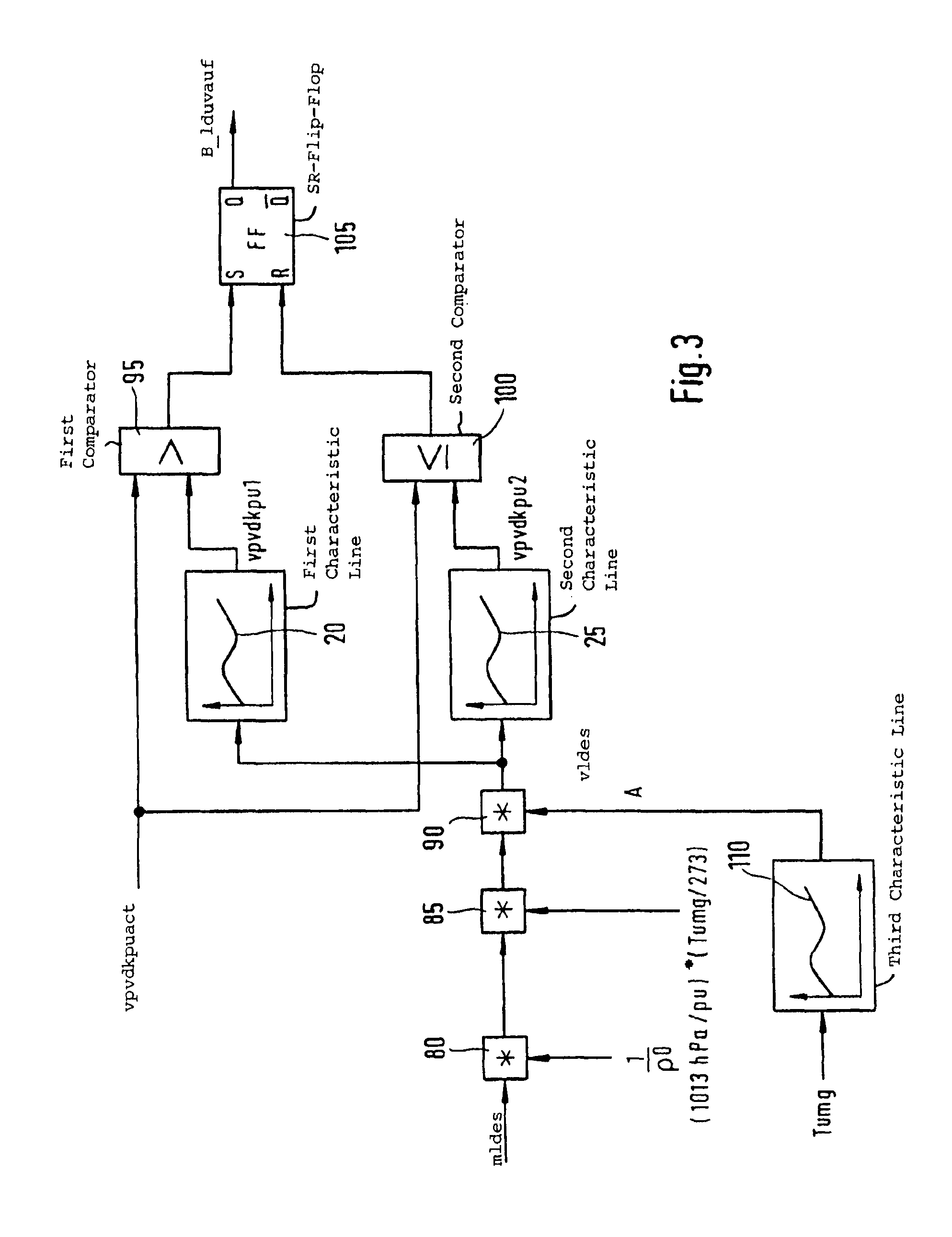
[0004]It is especially advantageous when a pressure ratio across the compressor is pregiven via the at least one pregiven characteristic line in dependence upon a desired air volume flow. A timely opening of the valve in the air path is ensured when utilizing the desired air volume flow as input quantity of the compressor characteristic field. A timely opening of the valve in the air path protects the shaft of the compressor and avoids unnecessary noise.
[0005]A simple possibility for driving the valve in the air path is provided with the pregiven air ratio.
[0006]It is especially advantageous when the valve is opened as soon as an actual value of the pressure ratio exceeds the pressure ratio, which is pregiven by a first pregiven characteristic line, and when the valve is closed as soon as an actual value of the pressure ratio drops below the pressure ratio pregiven by a second pregiven characteristic line. In this way, a hysteresis can be realized and, for a suitable spacing of these two characteristic lines, a continuous opening and closing of the valve in the air path is avoided.

Problems solved by technology

This leads to a pumping of the compressor which can load the shaft of the compressor or can cause disturbing noises.

Method used


Image

  • Method and arrangement for controlling an internal combustion engine
  • Method and arrangement for controlling an internal combustion engine
  • Method and arrangement for controlling an internal combustion engine

Examples


Embodiment Construction

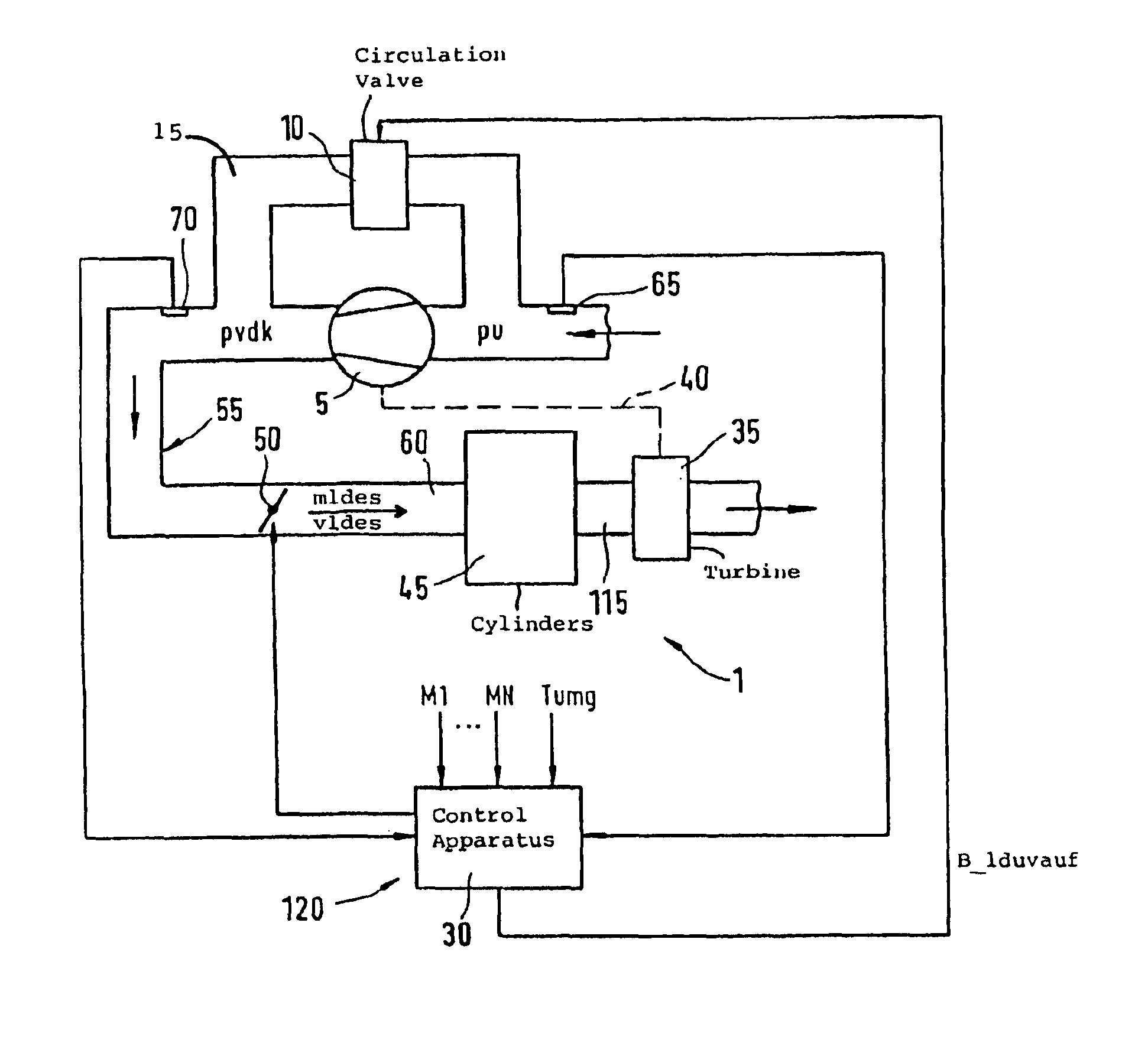
[0011]In FIG. 1, reference numeral 1 identifies an internal combustion engine which is here, by way of example, configured as a spark-ignition engine. The engine 1 includes one or several cylinders 45 to which fresh air is supplied via an air supply 55. The control of the desired air mass flow mldes takes place via a power actuating element 50 which, in this embodiment, is configured as a throttle flap. A section of the air supply 55 follows the throttle flap in the flow direction and is configured, in this embodiment, as an intake manifold 60. The intake manifold 60 is connected to the combustion chamber of the particular cylinder 45 by a corresponding inlet valve (not shown) of this particular cylinder 45. For example, in the case of the so-called intake manifold injection, the fuel can be injected into the intake manifold 60 by an injection valve (not shown in FIG. 1) in the flow direction ahead of the inlet valve. The exhaust gases, which arise during the combustion in the cylin...


PUM


Abstract

The invention is directed to a method and an arrangement for controlling an internal combustion engine (1) having a compressor (5) for compressing the air drawn in by suction by the engine (1). The compressor is especially an exhaust-gas turbocharger. With the method and arrangement, a requirement-proper and timely opening of a valve (10) of an air path (15) is ensured for avoiding compressor pumping. The air path (15) bypasses the compressor (5). The valve (10) of the air path (15), which bypasses the compressor (5), is controlled in dependence upon at least one pregiven characteristic line (20, 25) of a compressor characteristic field.

Description

BACKGROUND OF THE INVENTION[0001]Internal combustion engines are already known which include a compressor for compressing the air drawn in by suction by the engine. Compressors of this kind can, for example, be in the form of an exhaust-gas turbocharger. An air path is provided which bypasses the compressor and the air mass flow, which bypasses the compressor in this manner, is controlled by means of a so-called circulation valve. The air supply to the engine is controlled by means of a power adjusting member, for example, a throttle flap. When the throttle flap is suddenly closed, the air mass flow abruptly reverses into the intake manifold of the engine. The flow at the charger veins of the compressor is interrupted at high compression because of the low air mass flow. The compression collapses. A charging pressure again builds up at lower compression. This leads to a pumping of the compressor which can load the shaft of the compressor or can cause disturbing noises. If, however, ...

Claims


Application Information

Patent Timeline
IPC IPC(8): F02B33/44F02B37/16F02M69/04
CPCF02B37/16Y02T10/144F02M69/043Y02T10/12
Inventor WILD, ERNSTWEGENER, SABINEHILD, RAINER
Owner ROBERT BOSCH GMBH
Learn More