
Apparatus and method for correcting shake by controlling sampling timing of shake signal

a technology of shake signal and apparatus, applied in the field of image sensing apparatus, can solve the problems of correction errors produced in shake correction, the correction reference position cannot be ignored, and the correction reference position cannot be separated from the image barycentric position, etc., to achieve a drop of anti-shake effect and high anti-shake

Inactive Publication Date: 2006-01-03
CANON KK
View PDF19 Cites 65 Cited by
  • Summary
  • Abstract
  • Description
  • Claims
  • Application Information

AI Technical Summary

Benefits of technology

[0080]The present invention aims at solving the first problem, and has as its object to realize an image sensing apparatus and shake correction apparatus, which can prevent a drop of anti-shake effect resulting from a difference between the shake detection information sampling timing and shake correction timing, and can always obtain a high anti-shake effect independently of changes in image sensing condition, exposure condition, and the like such as a change in storage time period and the like.
[0087]According to this image sensing apparatus, since the sampling timing is set in correspondence with the drive condition at the image sensing timing of the image sensing means, the difference between the shake detection information sampling timing and shake correction timing can be appropriately removed.
[0113]The present invention proposed to solve the third problem has as its object to provide an image sensing method and apparatus which can implement shake correction, and allows a calculation means such as a microcomputer or the like to efficiently execute processing other than shake correction.

Problems solved by technology

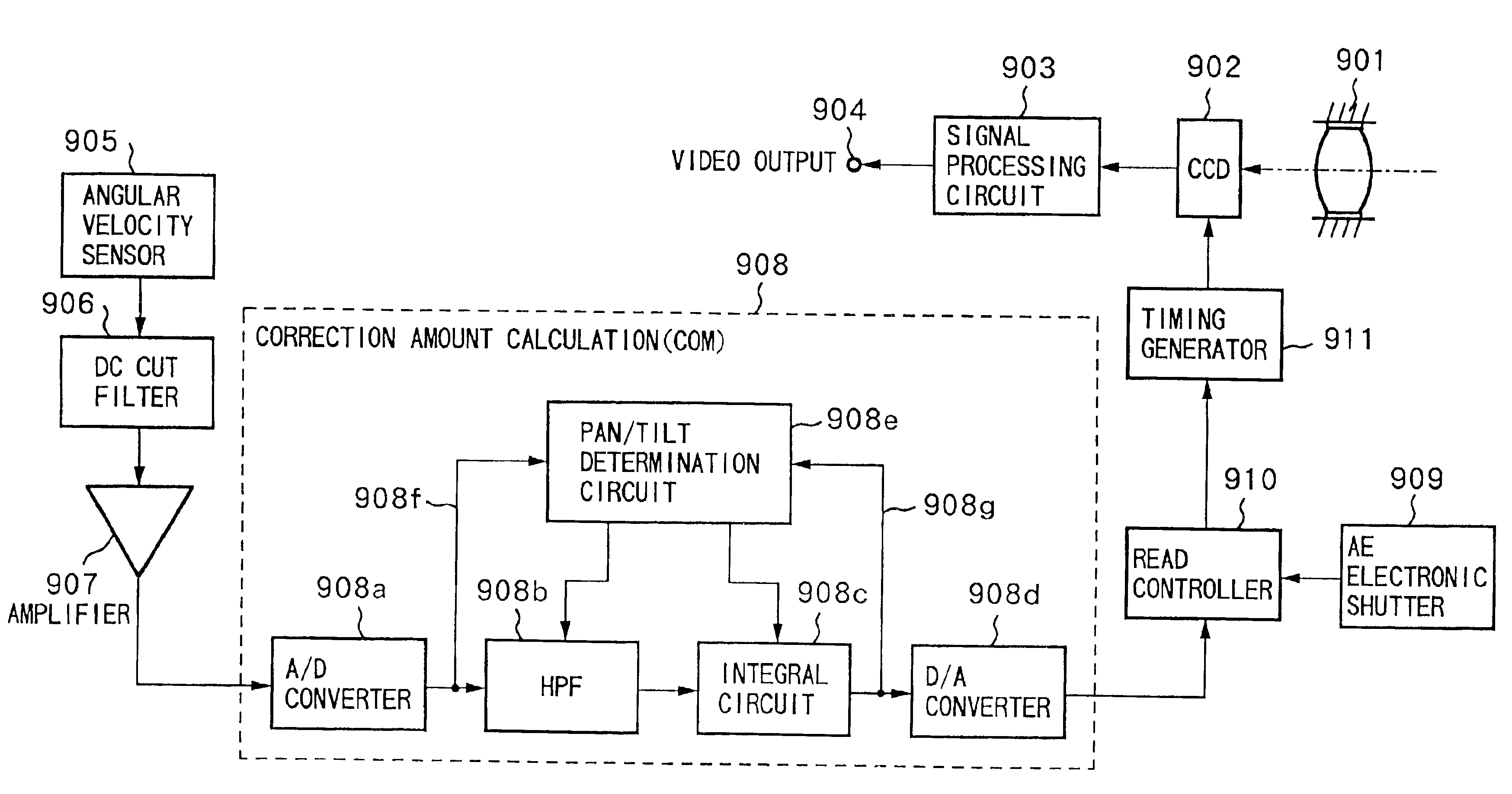
When storage & read control of the image sensing device 902 by the electronic shutter operation is made, the target correction reference position separates from the actual image barycentric position upon shake correction, and a video cannot be obtained with a sufficient anti-shake effect.
Hence, the problem that the correction reference position separates from the image barycentric position cannot be ignored.
As the second problem in the prior art, correction errors are produced in shake correction due to errors in the response characteristics of the shake detection means with respect to shake frequency.
More specifically, such correction errors are produced when the response characteristics of an angular velocity sensor such as a gyro sensor or the like used as shake detection means with respect to frequency worsens as the frequency becomes higher.
The first and second problems occur when the angular sensor signal is sampled once per field period.
However, in this conventional multi-sampling image sensing apparatus, when shake correction control is continuously done at the above-mentioned control timings, since the shake correction target values are calculated at fixed timings having equal time intervals, the use efficiency of a COM is poor.
The correction amount is discretely calculated in synchronism with the sampling timings of the angular velocity information, and the use efficiency of the COM itself is poor.
Such idle state of the COM frequently occurs if a large number of times of sampling of shake information is set.
Even when this idle period is used for another application, if that application requires continuous processing, such idle period is not suitable for the application since one field has already been divided into a plurality of periods.
If calculation processing such as auto-focus control that occupies a continuous time period and has higher priority is done, the correction amount calculation timing cannot be completed before the next sampling timing, and consequently, one sampling data is lost, i.e., effective correction data cannot be obtained.

Method used


Image

  • Apparatus and method for correcting shake by controlling sampling timing of shake signal
  • Apparatus and method for correcting shake by controlling sampling timing of shake signal
  • Apparatus and method for correcting shake by controlling sampling timing of shake signal

Examples


first embodiment

[0160]an image sensing apparatus according to the present invention will be described in detail below.

[0161]FIG. 8 is a block diagram showing a basic arrangement of a shake correction system of the image sensing apparatus according to the present invention. This image sensing apparatus is composed of an image sensing unit and camera shake correction unit. The image sensing unit (camera unit) has a lens 150, image sensing device 161, and signal processing circuit 162. The signal processing circuit 162 converts an electrical signal output from the image sensing device 161 into a standard video signal, and has a video output terminal 169, from which the standard video output is obtained.

[0162]The image sensing apparatus also has an angular velocity sensor 101 serving as a shake detection means, a DC cut filter 102, an amplifier 103, a computer (to be abbreviated as COM hereinafter) serving as a correction amount calculation means, an electronic shutter 181 serving as an AE control mean...

first modification

[0183] . . . First Modification

[0184]FIG. 11 is a block diagram showing the basic arrangement of the shake correction system of the image sensing apparatus according to a modification of the first embodiment.

[0185]The same reference numerals in FIG. 11 denote the same parts as in the first embodiment mentioned above, and a detailed description thereof will be omitted.

[0186]Referring to FIG. 11, this modification is different from the first embodiment in that the A / D converter 104a can receive and detect the operation timing of the electronic shutter 181 therefrom. More specifically, a control signal of the electronic shutter 181 is supplied to the A / D converter 104a to control the sampling timing of the A / D converter 104a.

[0187]As can be seen from the description of the first embodiment, the correction timing for shake correction largely depends on the timing of the electronic shutter, in other words, the sampling timing of the angular velocity signal can be determined if the elect...

second embodiment

[0202]FIG. 13 is a block diagram showing the basic arrangement of a shake correction system of an image sensing apparatus according to the

[0203]The same reference numerals in FIG. 13 denote the same parts as those in the first embodiment, and a detailed description thereof will be omitted. Referring to FIG. 13, unlike the arrangement of the first embodiment (FIG. 8), the second embodiment does not have any correction data determination unit 182 of the first embodiment. For this reason, in the image sensing apparatus of the second embodiment, one sampling timing of the A / D converter is set within one field period unlike the first embodiment.

[0204]The difference between the arrangements of the second embodiment and prior art (FIG. 1) lies in that a sampling timing controller 121 is added to the second embodiment.

[0205]The operation of the sampling timing controller 121 will be explained below with reference to the timing chart in FIG. 14.

[0206]FIG. 14 shows movement of an image stored...


PUM


Abstract

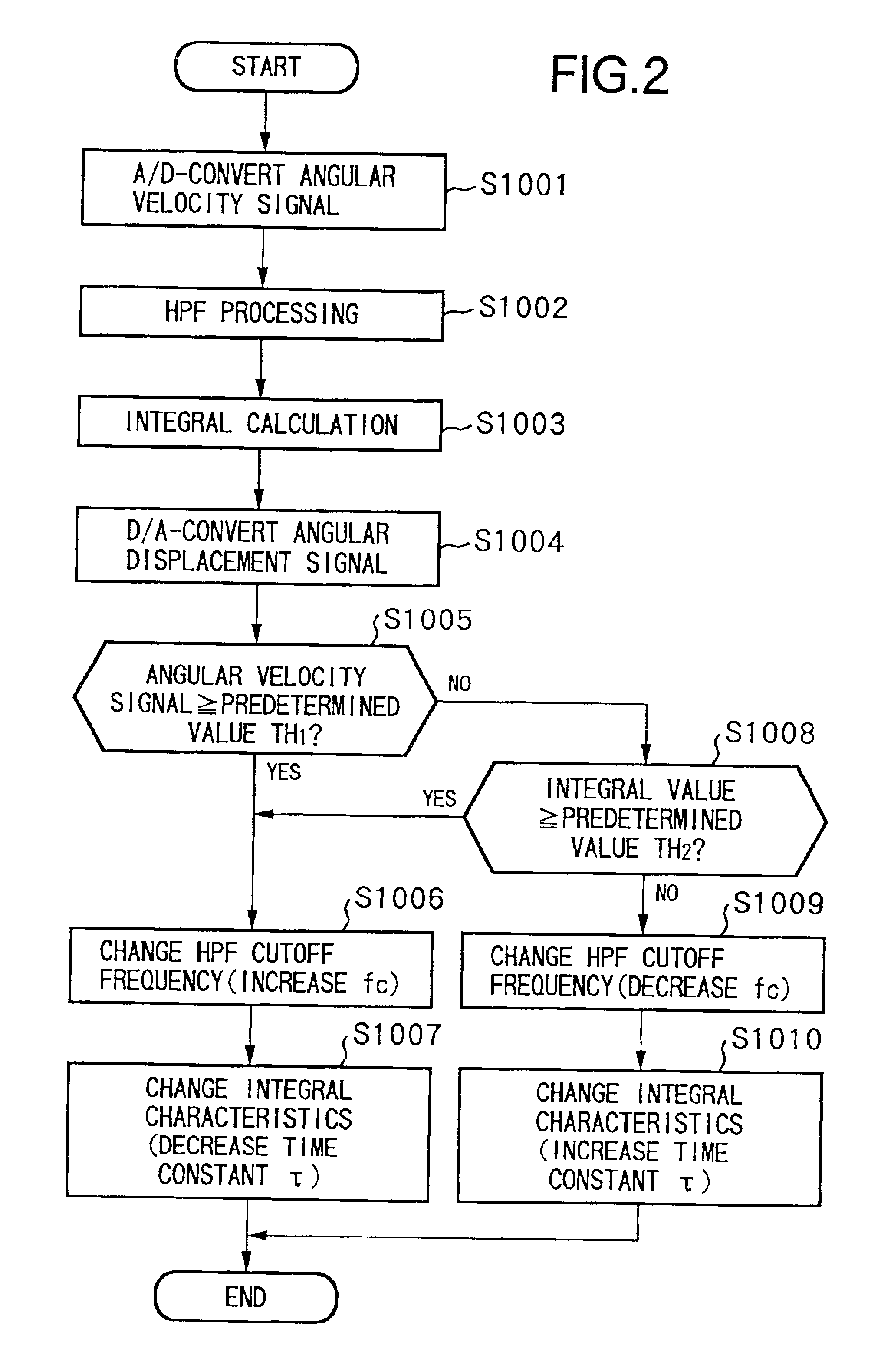
There is disclosed a shake prevention apparatus for compensating for a disturbance in an image resulting from a camera shake. A shake of a camera main body is measured by a gyro sensor. Upon sampling the output signal from the sensor by an A / D converter, a sampling timing corresponding to a shutter speed is set. Especially, a timing is generated so that the sampling timing corresponds to the central position of the charge storage period of a CCD.

Description

BACKGROUND OF THE INVENTION[0001]The present invention relates to an image sensing apparatus comprising an electronic anti-shake system that corrects a shake by electrically extracting a sensed image on the basis of shake information of a camera and an image sensing method, and to a shake correction apparatus and method.[0002]Conventionally, image sensing apparatuses such as video cameras and the like have a variety of automatic functions such as AE (auto exposure), AF (auto focus), and the like, and can sense and output a good image.[0003]Also, to compensate for a drop of sensed image quality resulting from a shake of an image sensing apparatus along with recent size reduction of video cameras and higher magnification of optical systems, various shake correction image sensing apparatuses that correct such camera shake have been proposed.[0004]FIG. 1 shows an example of the arrangement of a conventional image sensing apparatus with a shake correction function.[0005]Referring to FIG....

Claims


Application Information

Patent Timeline
Patent Type & Authority Patents(United States)
IPC IPC(8): H04N5/228H04N23/40
CPCH04N5/23248H04N5/23274H04N5/2327H04N5/23261H04N23/68H04N23/6815H04N23/6842H04N23/684
Inventor KAWAHARA, HIDEO
Owner CANON KK
Learn More