
Tail for attaching the trailing edge of one roll of tape to the leading edge of another roll of tape and method of using same

a technology of tail and tape, which is applied in the direction of photosensitive materials, instruments, mechanical control devices, etc., can solve the problems of not always causing the two pieces of tape to be joined, the adhesive is exposed to the moving tape for a short period of time, and the adhesive may not be able to release for a long tim

Inactive Publication Date: 2006-01-03
FORBO ADHESIVES
View PDF6 Cites 19 Cited by
  • Summary
  • Abstract
  • Description
  • Claims
  • Application Information

AI Technical Summary

Benefits of technology

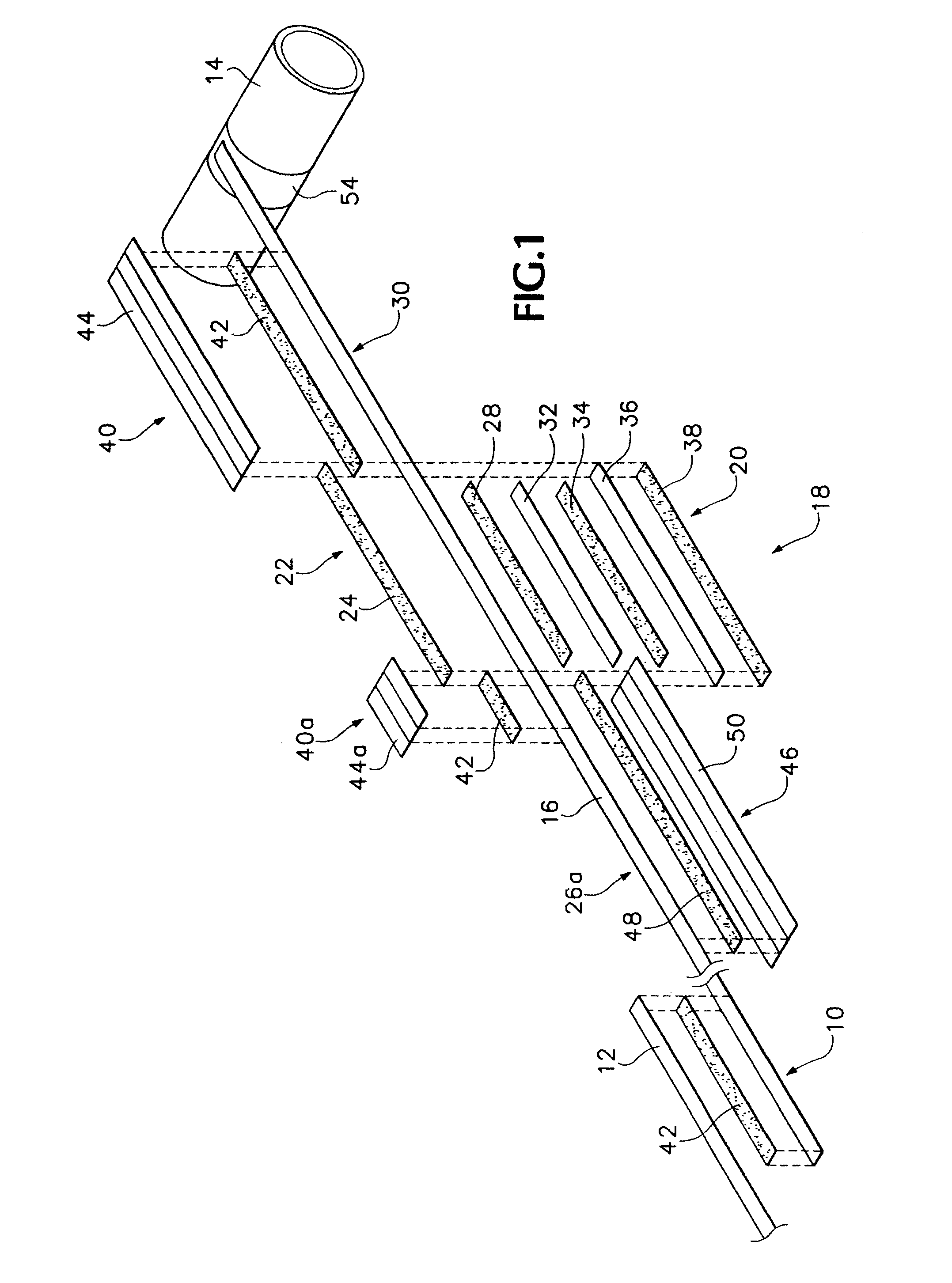
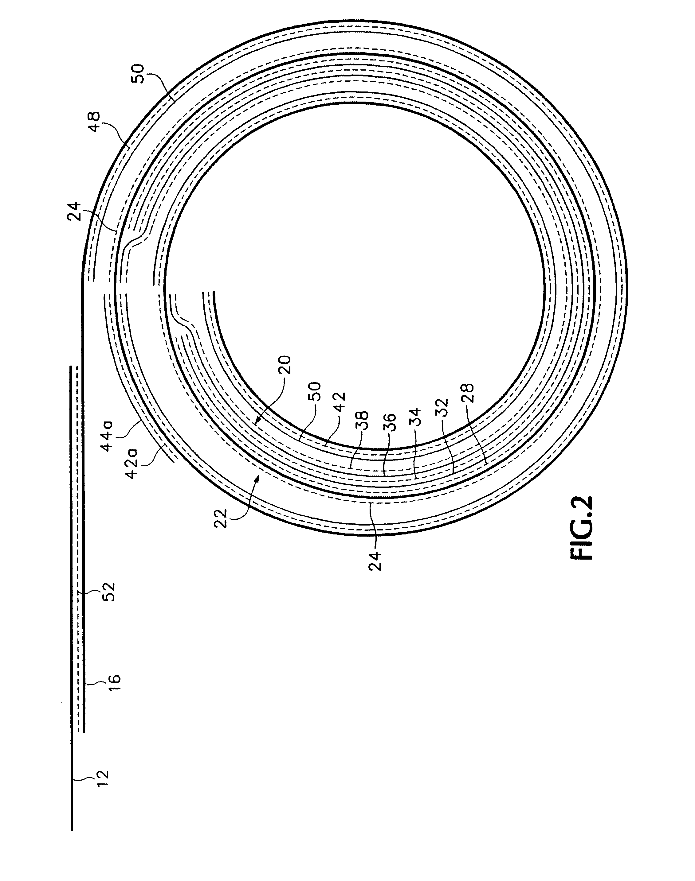
[0004]The subject invention overcomes the shortcomings and limitations of the prior art by providing a bulge in a tail that is attached to the trailing edge of the tape on each roll. This bulge has an adhesive coating on both sides. Protective elements are located on the tail on each side of the bulge in a manner that one of the protective elements covers the adhesive coating on each side of the bulge. As a result, when the tail is rolled onto a roll core the adhesive coating is protected by the protective element and will not stick to the roll core or to adjacent layers of the tail or tape. The protective element is configured such that it readily parts from the adhesive coating when the tail is unwound from the roll core.

Problems solved by technology

While simple and inexpensive, this system does not always cause the two pieces of tape to be joined.
In addition, the second roll can only be installed on the device which rotatively carries it in one direction in order that the adhesive side of the tape is facing the moving tape.
If adhesive is put on both sides of the tape to make it reversible, the adhesive on the other side may very well stick to the pincher rollers enough that the short period of time the adhesive is exposed to the moving tape may not be enough to release it.

Method used


Image

  • Tail for attaching the trailing edge of one roll of tape to the leading edge of another roll of tape and method of using same
  • Tail for attaching the trailing edge of one roll of tape to the leading edge of another roll of tape and method of using same
  • Tail for attaching the trailing edge of one roll of tape to the leading edge of another roll of tape and method of using same

Examples


Embodiment Construction

[0018]Referring to FIG. 1 of the drawings, a transfer tail 10 is attached to the trailing edge of a length of tape or tape-like material 12 which is wound onto a cylindrical roll core 14 to form a roll of tape (not shown). The purpose of the transfer tail is to automatically attach the trailing edge of the tape as it is removed from the roll to the leading edge of the tape from another roll without stopping the supply of tape to its intended application.

[0019]The tail 10 includes a tail base 16 which is made from the same or a similar material as the tape 12. The tail base preferably is 4–5 feet long, but its length is not limited. It does need to have a thickness which is similar to the thickness of the tape 12. Located on the tail base 16 near its trailing edge is a bulge 18 having a thickness which is greater than the thickness of the tail base. The bulge has an inside face 20 and an outside face 22, both of which have an adhesive coating.

[0020]In the preferred embodiment illustr...


PUM

PropertyMeasurementUnit
lengthaaaaaaaaaa
thicknessaaaaaaaaaa
lengthaaaaaaaaaa

Abstract

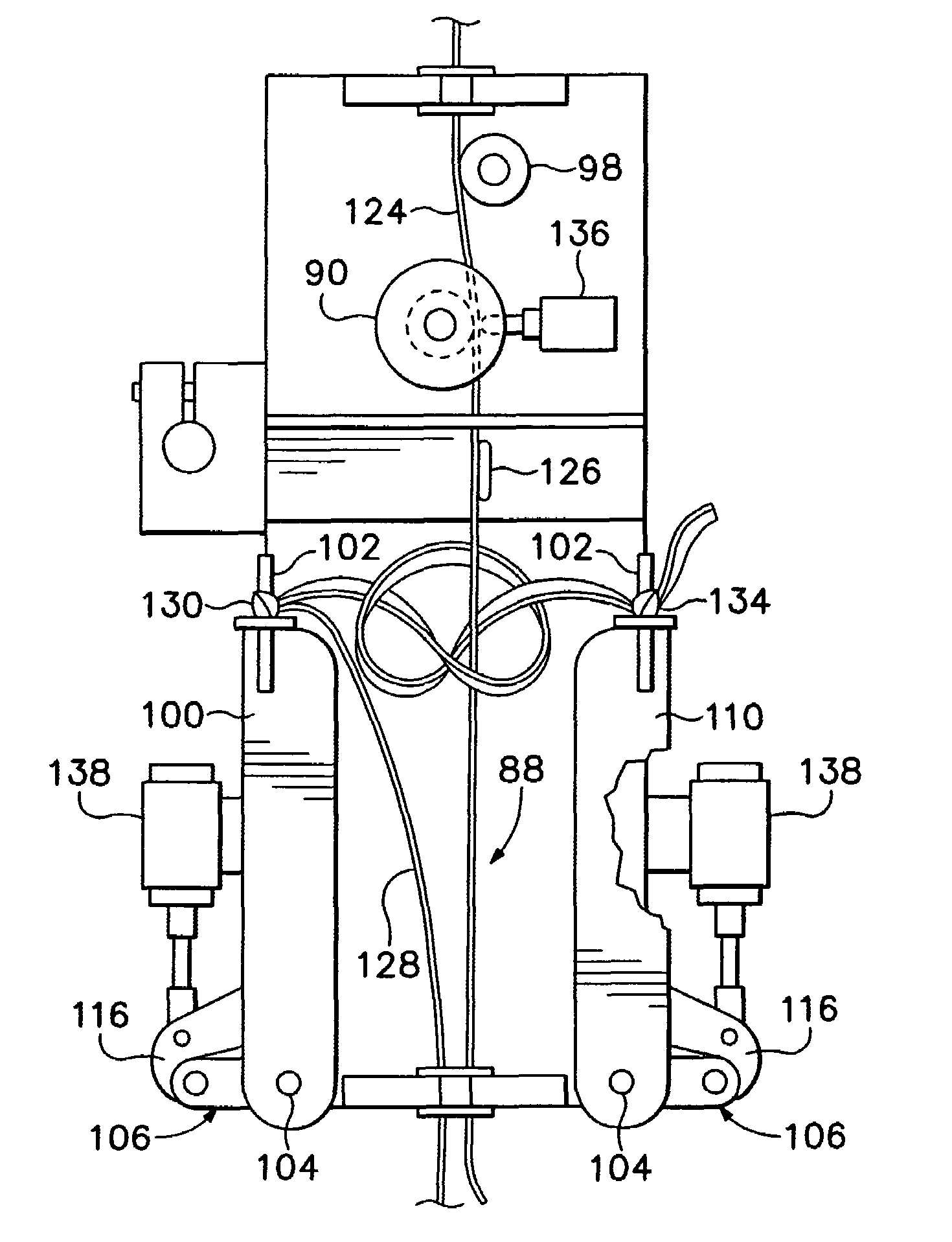
A tape splicing mechanism joins the tail of one tape to the leading edge of another tape. A frame defines a passageway along which the tape passes. A pair of arms rotatably attached to the frame have projecting posts and rotate between a first position where the posts are closer to the pathway and a second position where they are further from the pathway. The arms are urged toward the first position and a catch mechanism holds them in the second position until released by a release mechanism when a release indicia in the first tape passes. The leading edge of the second tape is looped around the first tape to form a loose knot and is tied to the post on each side of the first tape. When the arms are released they move to the second position and tighten the knot.

Description

RELATED APPLICATIONS[0001]This application is a continuation-in-part of application Ser. No. 09 / 963,190 filed Sep. 25, 2001, now U.S. Pat. No. 6,596,111, issued Jul. 22, 2003.BACKGROUND AND SUMMARY OF THE INVENTION[0002]The subject invention relates to a tail which is used to attach the trailing edge of tape from one roll to the leading edge of tape from another roll and to a method of using this tail to join rolls of tape together.[0003]There are numerous applications where a continuous supply of tape material must be provided. When this occurs there needs to be a way of attaching the trailing edge of one roll of tape to the leading edge of another roll of tape without interrupting the feeding of the tape. This can be accomplished by placing a mechanical fastening device on the tape or by adhesively joining the two tapes together. An example of the latter is the system disclosed in U.S. patent application Ser. No. 09 / 398,153, now U.S. Pat. No. 6,325,324. Here the trailing edge of t...

Claims


Application Information

Patent Timeline
Patent Type & Authority Patents(United States)
IPC IPC(8): B65H21/02B65H19/10B65H19/18
CPCB65H19/102B65H19/1852B65H19/1873B65H2701/37B65H2301/4621
Inventor CYR, GILLESDALEBOUT, ELVINWILLADSON, RONALD L.
Owner FORBO ADHESIVES
Learn More