
Power generation system using a combustion system and a fuel cell

a technology of combustion system and fuel cell, which is applied in the direction of reciprocating combination engines, marine propulsion, vessel construction, etc., can solve the problems of limited capacity for both duration and output power, damage to the turbine, and add additional mechanical complexity, so as to achieve the effect of more maneuverability

Active Publication Date: 2005-12-27
LOCKHEED MARTIN CORP
View PDF14 Cites 40 Cited by
  • Summary
  • Abstract
  • Description
  • Claims
  • Application Information

AI Technical Summary

Benefits of technology

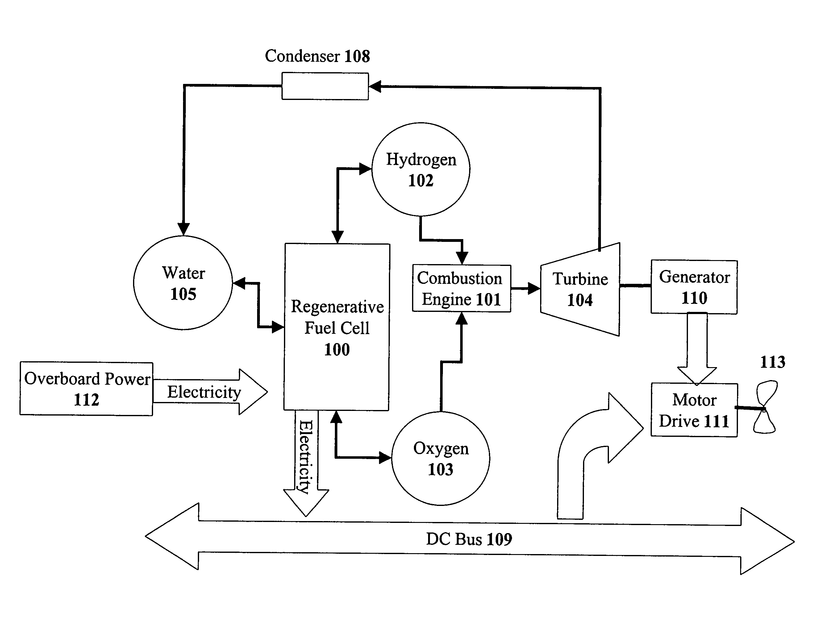
[0008]Therefore, it is an object of the present invention to provide a marine vessel that is neutrally buoyant so that the vessel does not rise or sink by providing a closed-loop power system in which mass is not ejected out of the vessel. Closed systems do not eject mass into the surroundings, which makes the vessel neutrally buoyant and potentially more maneuverable. Furthermore, it is another object of the present invention to be able to recharge or regenerate the power system simply, by use of an electrical connection.
[0012]Using electricity supplied by an outside power supply, the regenerative fuel cell can reduce the water stored in the onboard water supply into hydrogen and oxygen, which is stored back into the hydrogen supply and the oxygen supply, respectively. The marine vessel can be an underwater vessel, which can be either manned or unmanned.

Problems solved by technology

These traditional power / propulsion generation systems for submersible vessels have relied on stored electrical power, which has limited capacities for both duration and output power.
However, these metal reactions can produce ceramic particles that can damage the turbine.
However, this adds additional mechanical complexity and the potential for leaks into to the system.
Further, by expelling this mass from the vessel, the vessel becomes more buoyant and tends to rise, thus making it more likely that the vehicle will be spotted or detected.
This is a problem for vehicles involved in covert operations.

Method used


Image

  • Power generation system using a combustion system and a fuel cell
  • Power generation system using a combustion system and a fuel cell
  • Power generation system using a combustion system and a fuel cell

Examples


Embodiment Construction

[0019]Although this invention is applicable to numerous and various types of power generation and propulsion systems for marine vessels, it has been found particularly useful in the environment of power generation systems for small-scale underwater vessels and UUVs. Therefore, without limiting the applicability of the invention to underwater vessels, the invention will be described in such environment.

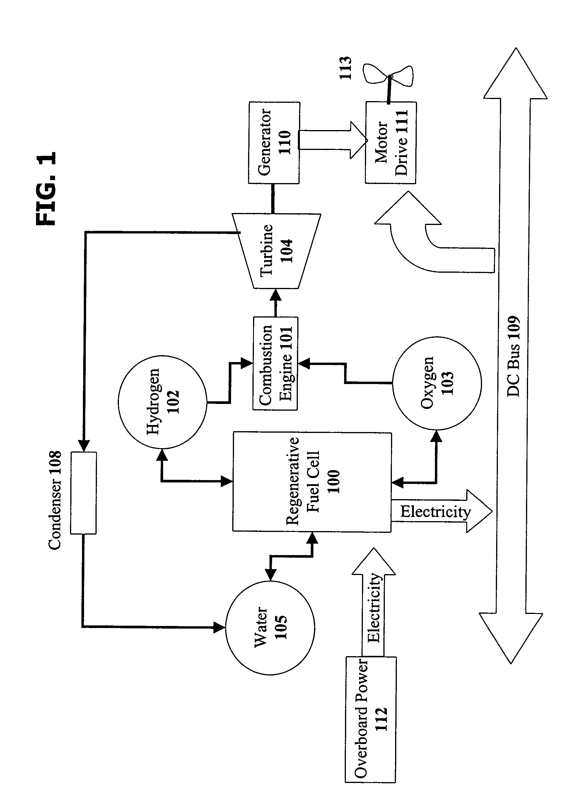
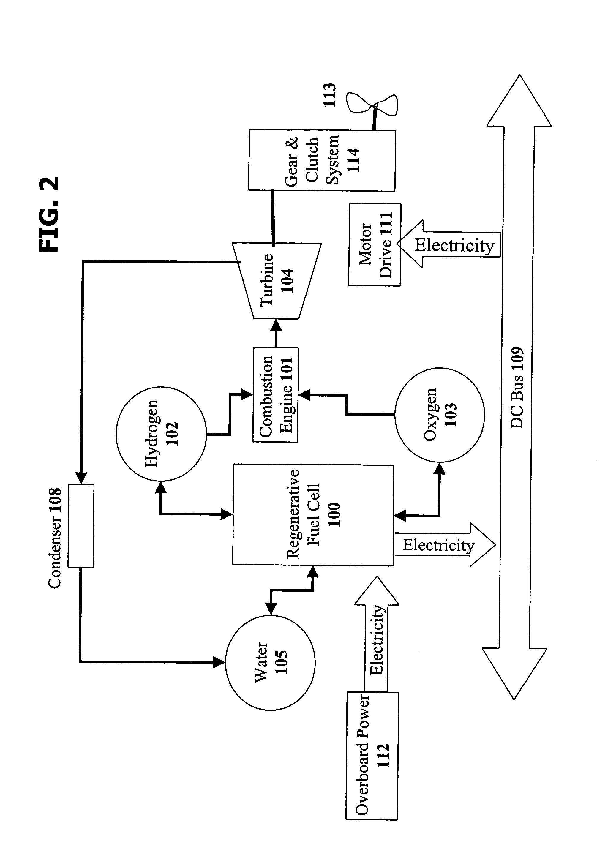
[0020]With reference to FIG. 1, there is a schematic representation of a closed loop power system for an underwater vehicle. Hydrogen is stored in a hydrogen supply 102 and oxygen is stored in an oxygen supply 103. The hydrogen supply 102 and oxygen supply 103 could be pressurized tanks containing the fuel and oxidizer, respectively, with the related control and safety elements. The hydrogen supply 102 and the oxygen supply 103 are in fluid communication with a regenerative fuel cell 100. Water is stored in a water supply 105, which is in fluid communication with the regenerative fuel ...


PUM


Abstract

A regenerative fuel cell is combined with a combustion engine such as a Pulse Detonation Engine (PDE) to create a closed-loop power generation system. Stored hydrogen and oxygen are used by the regenerative fuel cell, and by the combustion engine, in which the reaction of the hydrogen and oxygen produces water in the gas phase (steam). The steam is used to generate work from a turbine shaft, which is used to drive a propulsion system for the marine vessel. After the steam passes through the turbine, the steam is cooled back to liquid water by a condenser, and stored with the water produced by the regenerative fuel cell. The stored water can be converted back into hydrogen and oxygen by using electrical power external to the closed-loop system. After regeneration of the water into hydrogen and oxygen, the closed-loop power system would be ready for operation again.

Description

BACKGROUND OF THE INVENTION[0001]1. Field of the Invention[0002]The present invention relates to power generation systems for marine vessels, and more specifically, to a closed-loop power and propulsion generation system for an underwater vessel combining a Pulse Detonation Engine with a regenerative fuel cell.[0003]2. Prior Art[0004]Vehicles that operate underwater are useful for performing tasks below the sea surface in such fields as deep-water salvage operations, navy and marine operations, underwater telecommunications, offshore petroleum and mining, and oceanographic research. Many of these applications are completed by small-scale underwater vehicles that can be either manned or unmanned (remotely operated). These unmanned vehicles are commonly known as Unmanned Underwater Vehicles (UUVs).[0005]Generally, these small-scale underwater vessels have used conventional power systems. These traditional power / propulsion generation systems for submersible vessels have relied on store...

Claims


Application Information

Patent Timeline
Patent Type & Authority Patents(United States)
IPC IPC(8): B63H21/20F01B21/04F01K23/00F01K25/00F02B73/00
CPCF01K25/005B63H21/17B63H2021/003Y02T90/38Y02T70/5236Y02T70/5209Y02T90/46Y02T70/50Y02T90/40
Inventor GOLDMEER, JEFFREYCUEMAN, MICHAEL KENTDURLING, MICHAEL
Owner LOCKHEED MARTIN CORP
Learn More