
Blow open moving contact assembly for electric power switching apparatus with a very high current interruption rating

a technology of electric power switching apparatus and open moving contact, which is applied in the direction of circuit-breaking switches, circuit-breaking switches for excess current, circuit-breaking switch details, etc., can solve the problem of limiting actual current to less, achieve good gas seal, enhance arc extinguishment, and blow reliably

Active Publication Date: 2005-12-20
EATON INTELLIGENT POWER LTD
View PDF11 Cites 36 Cited by
  • Summary
  • Abstract
  • Description
  • Claims
  • Application Information

AI Technical Summary

Benefits of technology

The invention is about a moving carrier assembly for an electric power switching apparatus that is designed to interrupt very high currents. The assembly is stable and reliable enough to maintain its position until the threshold current is reached, and then it can safely and reliably blow open. The assembly includes a carrier body, carrier legs, an outer carrier, an inner carrier, contact fingers, a cam follower pin, and cam springs. The cam profile is designed to ensure that the inner carrier is biased to the withstand position when the current is below a certain threshold, and it is quickly pivoted to the blow open position when the current exceeds the threshold. The assembly also includes a gas shield to enhance the arc extinguishment and prevent flashover. Overall, the invention provides a reliable and effective solution for interrupting high currents in electric power switching applications.

Problems solved by technology

This blow opening is driven by the electromagnetic repulsion force on the contacts and is very fast, limiting the actual current to less than the available fault current.

Method used


Image

  • Blow open moving contact assembly for electric power switching apparatus with a very high current interruption rating
  • Blow open moving contact assembly for electric power switching apparatus with a very high current interruption rating
  • Blow open moving contact assembly for electric power switching apparatus with a very high current interruption rating

Examples


Embodiment Construction

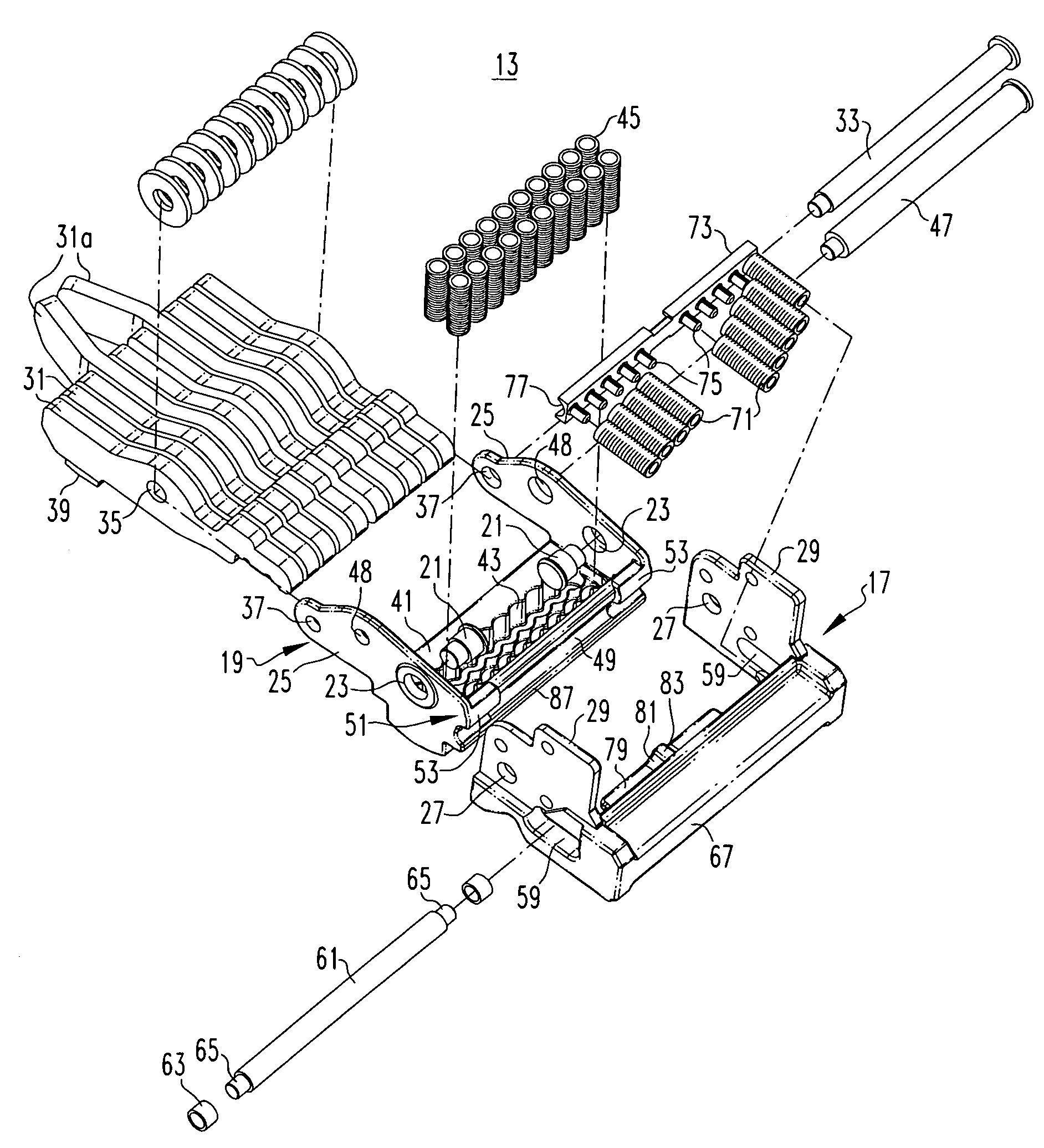
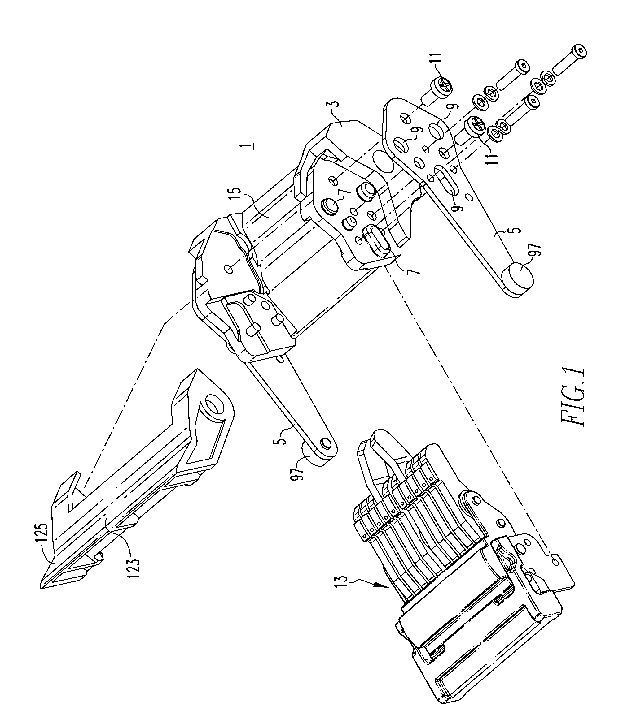
[0022]Referring to FIGS. 1 through 6, the exemplary embodiment of the moving contact assembly 1 incorporating aspects of the invention includes a carrier body 3 molded of an electrically insulative resin. A pair of carrier legs 5 are locked to the carrier body 3 by a number of molded protrusions 7 that seat in complementary openings 9 in the legs, and are held in place by fasteners 11 so that the connection between the legs and the carrier body is rigid. A sub-assembly 13 is received in a cavity 15 in the carrier body 3.

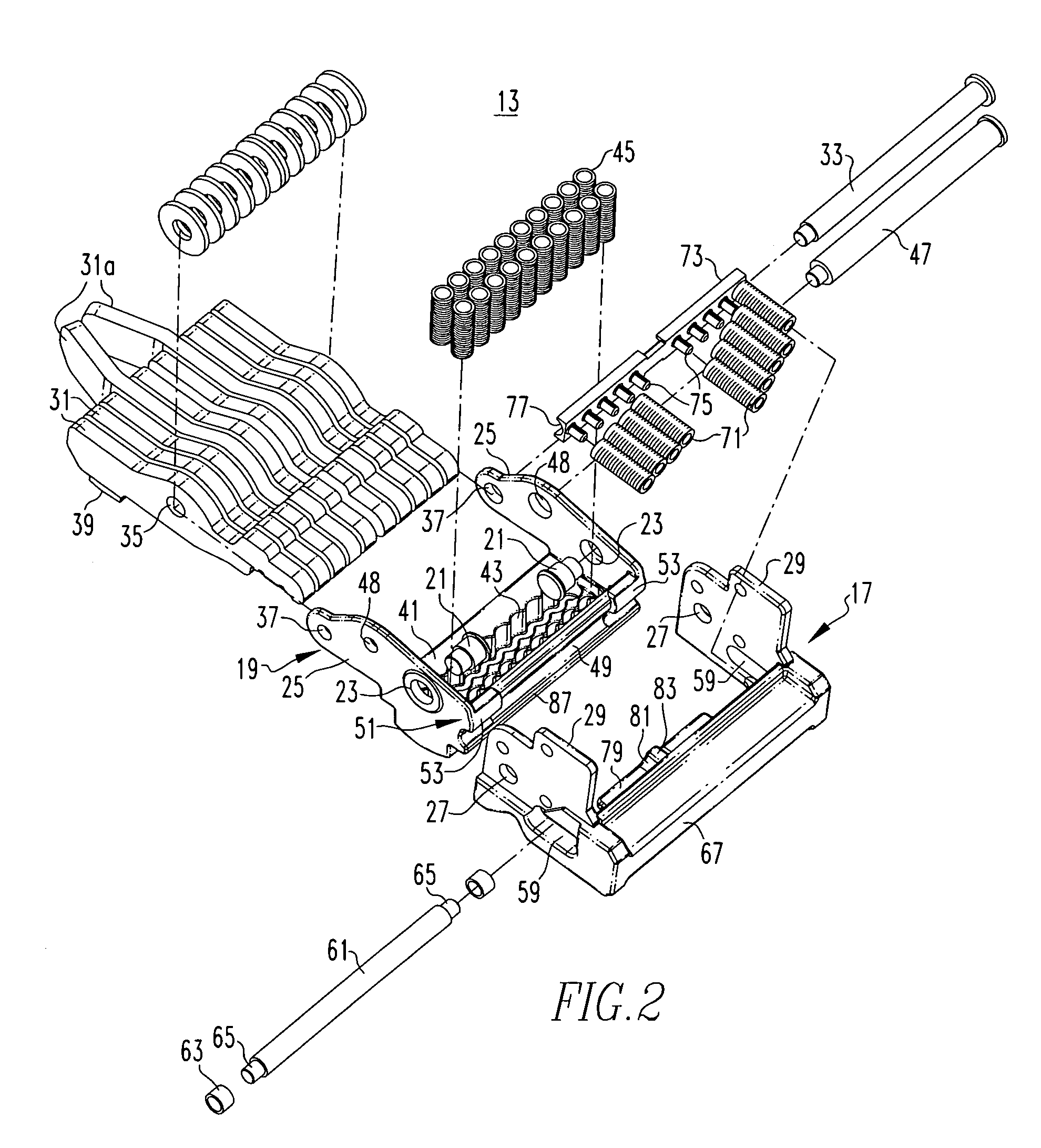
[0023]The sub-assembly 13, which is shown exploded in FIG. 2, includes an outer carrier 17 that is firmly secured in the carrier body 3. An inner carrier 19 is pivotally mounted to the outer carrier 17 by pivot pins 21 that pass through holes 23 in inner carrier sidewalls 25 and seat in holes 27 in outer carrier sidewalls 29. A plurality of contact fingers 31 are pivotally mounted on the inner carrier sidewalls 25 by a contact finger pin 33 that passes through holes ...


PUM


Abstract

A moving contact assembly for a high-current interruption electric power switching apparatus has an inner carrier for the contact fingers that is rigidly held in a withstand position in an outer carrier by a spring biased cam follower pin engaging a cam profile on the inner carrier and configured to positively seat an inner carrier stop against an outer carrier stop on the outer carrier and to rapidly drive the inner carrier to a blow open position in response to a fault. The cam profile has an extended width divided between spaced apart cam profile sections to absorb the high closing and withstand forces. An abutment on the outer carrier resists bowing of the cam follower pin between the cam profile sections. Complementary convex and concave partial cylindrical surfaces on the inner carrier and a gas shield on the moving assembly carrier body maintain an arc gas seal during blow open.

Description

BACKGROUND OF THE INVENTION[0001]1. Field of the Invention[0002]This invention relates to electric power switching apparatus and in particular to blow open moving contact assemblies for such apparatus with very high current interruption ratings.[0003]2. Background Information[0004]Power circuit breakers typically are used as a main breaker in a power distribution system having additional downstream branch circuit breakers. They are also used as transfer switches for switching between alternative power sources, and as network protectors in larger distribution systems. In such systems, the power circuit breaker must have sufficient withstand capability to allow a downstream breaker to respond to a fault in order to minimize the extent of the outage. However, in the instance of a very large fault, such as a fault just downstream of the power breaker, it is desirable to have the power breaker respond promptly to limit the fault current. It is known to provide a power circuit breaker wit...

Claims


Application Information

Patent Timeline
Patent Type & Authority Patents(United States)
IPC IPC(8): H01H1/22H01H77/10H01H83/00
CPCH01H1/225H01H1/226H01H77/102H01H77/104H01H2009/305H01H33/08H01H73/18
Inventor RAKUS, PAUL R.PENDRICK, THOMAS C.SHEA, JOHN J.MILLER, JEFFREY A.SISSON, GLEN C.SCHULMAN, MICHAEL B.CHIEN, YUN-KO N.
Owner EATON INTELLIGENT POWER LTD
Learn More